Joe2Lmaker
Well-known member
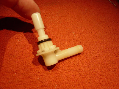
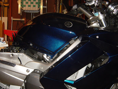
I find myself shooting off on another tangent. I started out installing a bulkhead fitting, a necessary step closer to installing an auxiliary tank.
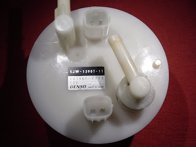
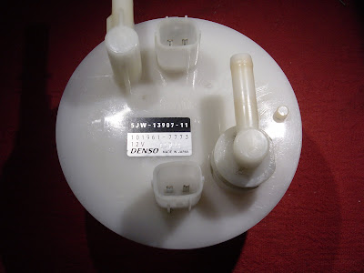
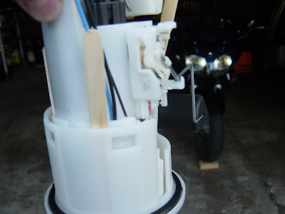
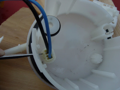
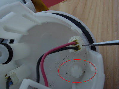
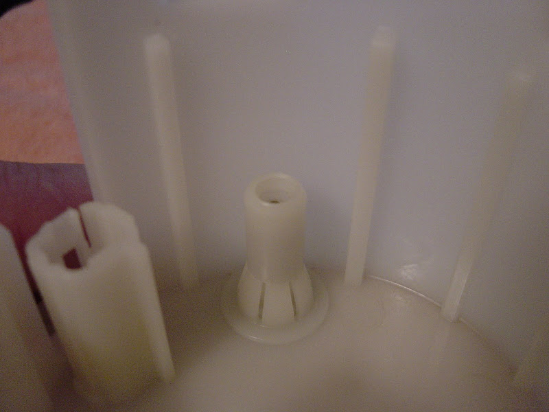
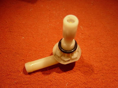
While studying for the project, I saw this feature in the photos:
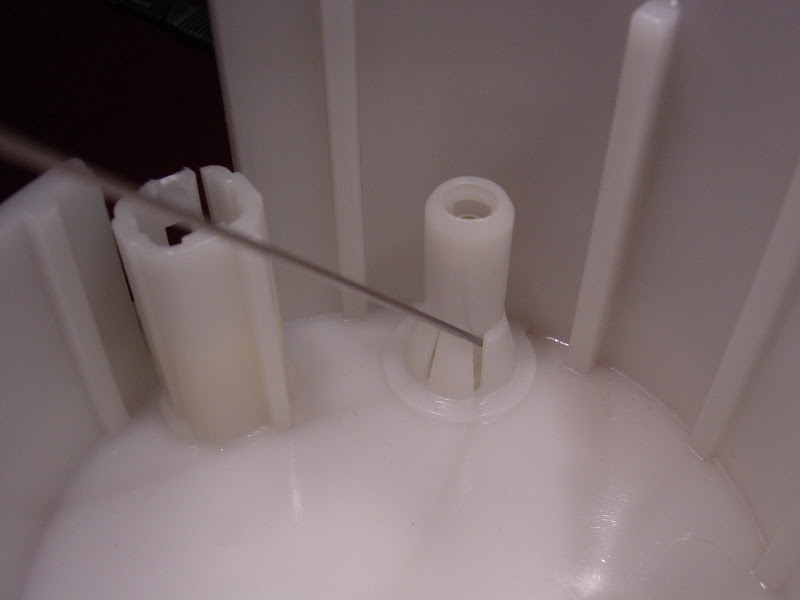
DENSO probably has another fuel pump that uses that feature, but the GenII FJR doesn't need it. Before this part was molded, inserts were removed from the tool (mold) so that the plastic could flow into details that would otherwise be shut-off.
I'm considering adding a fitting here (line from my auxiliary tank) instead of drilling through the FJR's tank. It's too bad this isn't a Walbro fuel pump. I could probably acquire the part instead of reverse engineering this one.")
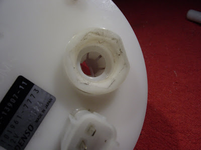
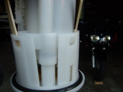
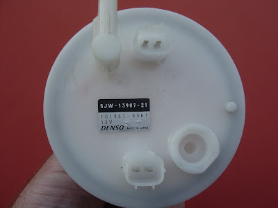
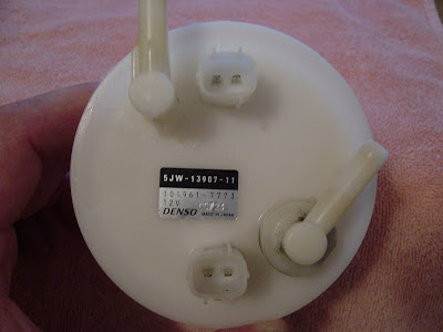
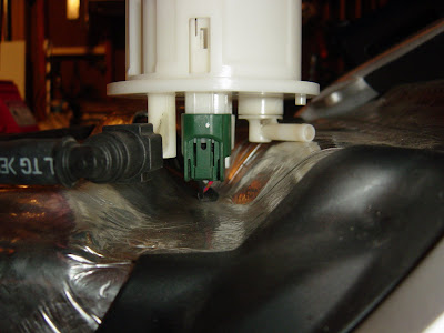
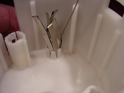
Before any modifications can be made, a little more disassembly is necessary:
Edited for clarity: Gently pry each of the window snap features on the base (flange) off its corresponding catch on pump holder.
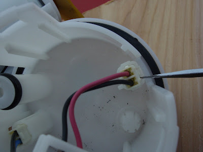
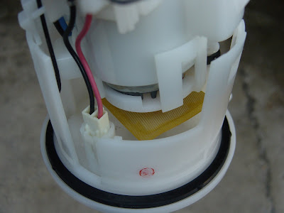
After the base (flange) is separated from the pump housing, remove the connections for the fuel level sending unit and the pump.
 [SIZE=36pt] [/SIZE]
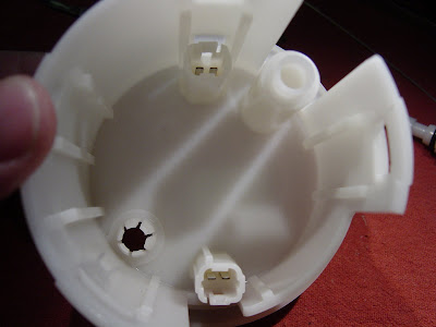
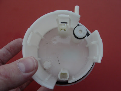
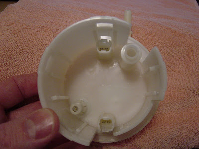
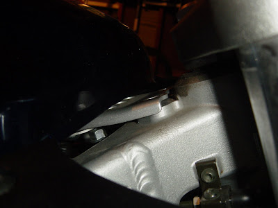
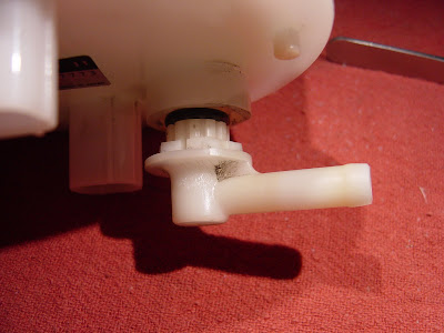
This is the base after it's separated from the pump housing:
 [SIZE=36pt] [/SIZE]
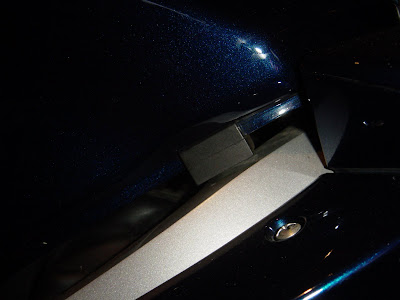
Now the fun part...
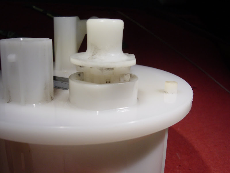
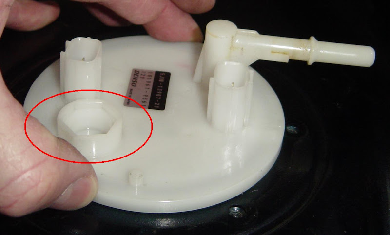
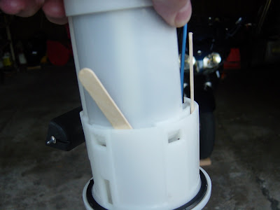
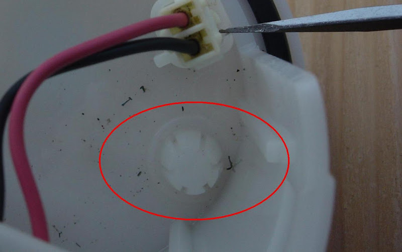
While studying for the project, I saw this feature in the photos:
DENSO probably has another fuel pump that uses that feature, but the GenII FJR doesn't need it. Before this part was molded, inserts were removed from the tool (mold) so that the plastic could flow into details that would otherwise be shut-off.
I'm considering adding a fitting here (line from my auxiliary tank) instead of drilling through the FJR's tank. It's too bad this isn't a Walbro fuel pump. I could probably acquire the part instead of reverse engineering this one.
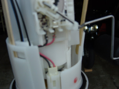
Before any modifications can be made, a little more disassembly is necessary:
Edited for clarity: Gently pry each of the window snap features on the base (flange) off its corresponding catch on pump holder.
After the base (flange) is separated from the pump housing, remove the connections for the fuel level sending unit and the pump.
This is the base after it's separated from the pump housing:
Now the fun part...
Last edited by a moderator:
 [SIZE=36pt][/SIZE]