I just completed doing the dreaded valve adjustment myself after reading Torch's and Fred W's excellent procedures. I had some questions afterwards and wanted to be sure I didn't screw up the cam timing when installing the cam shafts. Yes, you can do it without removing the cams, but I turned the motor over with the cam chain tensioner released and I was pretty sure I jumped a tooth.
Here are a few things I found that might be helpful while following Torch's procedure.
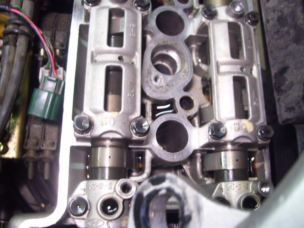
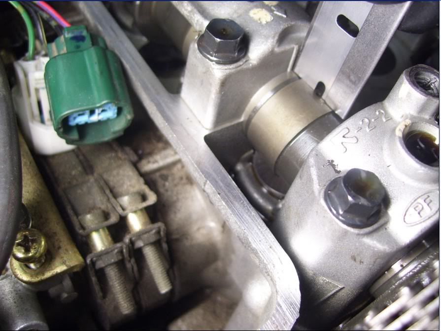
Pull the right side lower fairing (I didn't have to remove the left lower fairing) Remove the timing cover and rotate the crank clockwise only until the letter "T" lines up with engine case seam on the left. Check to make sure the #1 cylinder intake cam lobe is at about 10 o'clock and the #1 cylinder exhaust cam lobe is at about 2 o'clock. If they are not, rotate the crank one more turn. This puts the #1 one cylinder on the compression stroke. The dots on the right end of cam shafts should also line up with the arrows on the cams caps. Then and only then release the cam chain tensioner. Don't rotate the motor with the chain tension released or you will jump a tooth on the cam sprockets.
A twelve point 10 mm box end wrench will allow you to remove the bolt in the end of the cam chain tensioner. The screw driver used to turn the tensioning screw has to go into the hole the bolt came out of so it must be smaller than the bolt. I had to grind down the flair on the end of the shaft to get it to go into the hole.
A note on the timing cover. There are two alignment pins, one short and one long. Usually they will both stay in the engine case. Be aware that the long pin is the pivot for the rear cam chain tensioning rail. If the pin comes out with the cover, it must be replaced in the engine case holding the bottom of the tensioning rail.
When removing the bucket lifters and shims, a magnet works well. Usually both the bucket and shim will come out together.
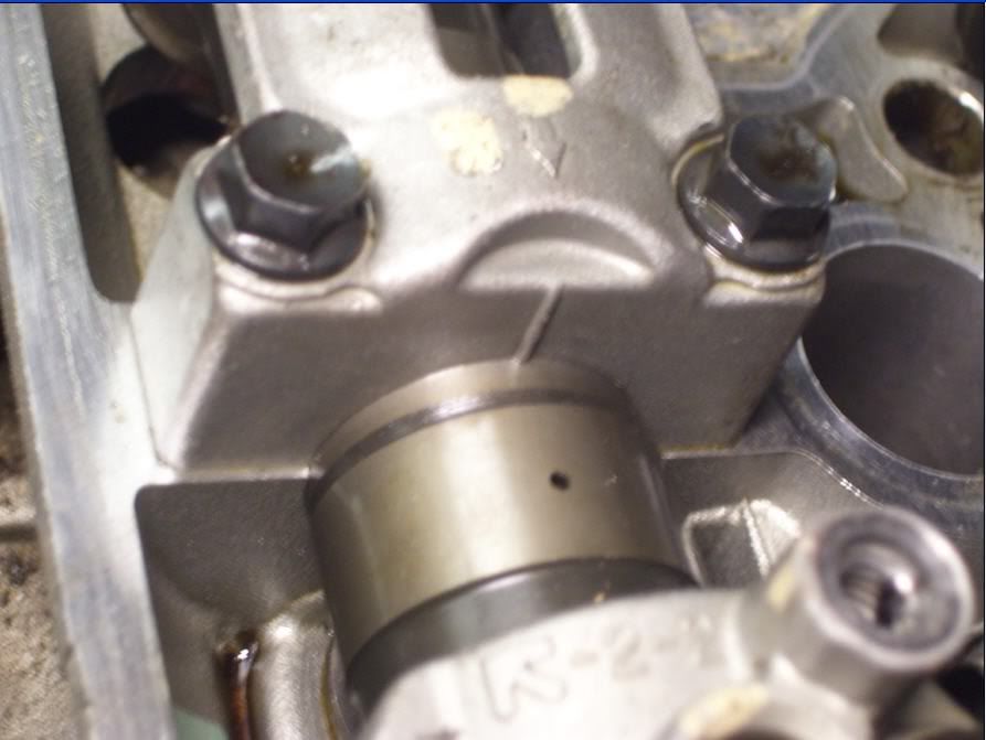
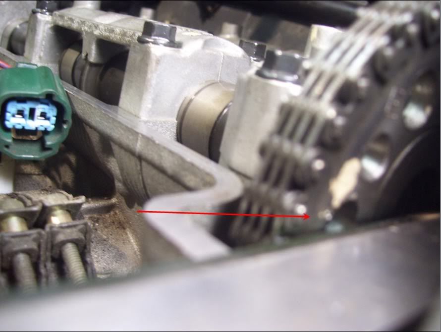
Do the exhaust cam first. It is the hardest. It is very hard to see when the cam is exactly in the right position by lining up the dot with cam cap arrow. One tooth off is only 9 1/2 degrees and that is about a tenth of an inch on the shaft. There are timing marks on the sprockets, but they are on the outside of the sprockets. The frame rail blocks your view of these marks except for the rear mark on the intake cam. I transfered the location of the timing marks to the inside of the exhaust cam sprocket and made a small mark on the sprocket with a file. These marks must line up with top of engine head while the # 1 cylinder exhaust lobe is at about two o'clock.
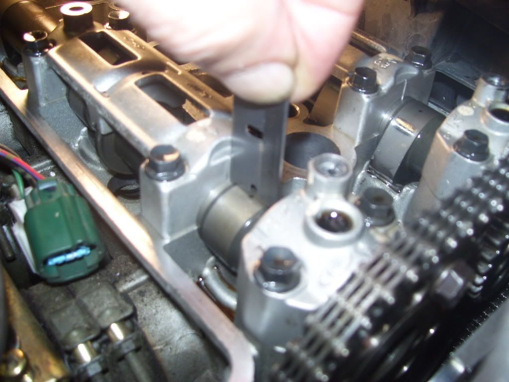
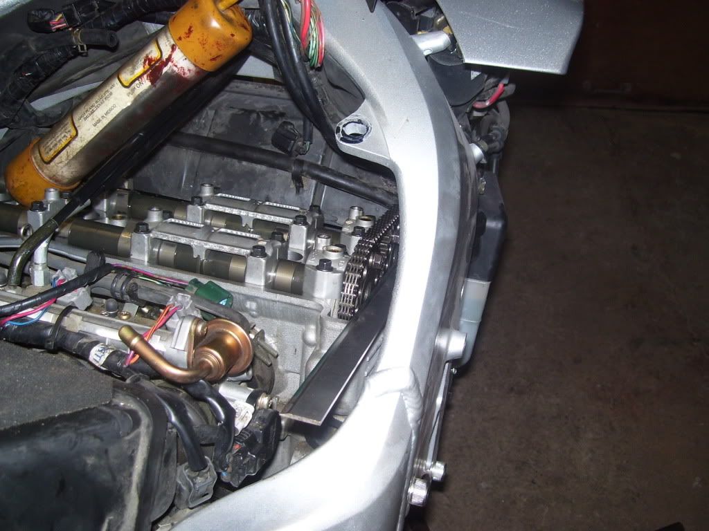
When re-installing the exhaust cam, be sure the cam chain is tight coming up from the crank on the front. If you have done this correctly, the cam will not sit down into the cam shaft races all the way, due to the lobes making contact with the valve lifters on number 2 and 3 cylinders. Tighten all the cam shafts cap bolts a little at a time, and the shaft will push the valves partially open.
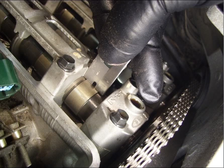
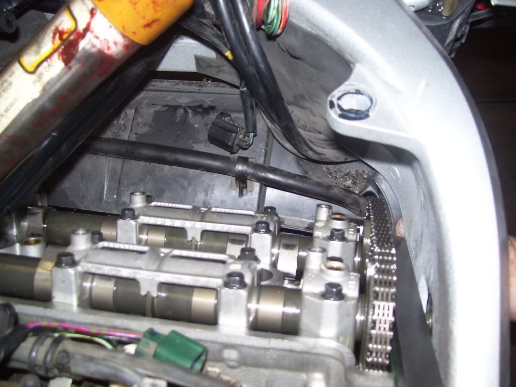
The intake cam is easier to do. The number one cam lobe should be at about 10 o'clock with dot lined up with arrow and the timing mark on the outside of the cam sprocket lined with the edge of the head. You can just see it above the frame rail. Bolt the shaft down as above. Check and re-check that all marks are lined up and re-tension the cam chain tensioner.
Rotate the motor several times and re-check the valve clearances.
Replacing the bolt in the cam chain tensioner is difficult since there is no room to get your fingers in there. After several attempts, mine went in easily with this method. I bent a wire in the shape of a hook that was sized to go around the threads of the bolt. This let me hold the bolt in place in front of the hole then spin it in with one finger.
I elected to remove the induction AIR hoses and replace the ports in the valve cover with WynPro's covers. This cleans up the cramped area under the tank, but more importantly, it makes replacing the valve cover much easier without pipes sticking up and rubbing on radiator hose and the wiring. I used the metal plug and a piece of the removed hose assembly and clamps to plug the air box port. The Gen2 engines may not have this plug on the hose assembly. I never did figure out why it was there on the Gen1 engines.
I hope this adds to the collective wisdom doing this procedure.
Here are a few things I found that might be helpful while following Torch's procedure.
Pull the right side lower fairing (I didn't have to remove the left lower fairing) Remove the timing cover and rotate the crank clockwise only until the letter "T" lines up with engine case seam on the left. Check to make sure the #1 cylinder intake cam lobe is at about 10 o'clock and the #1 cylinder exhaust cam lobe is at about 2 o'clock. If they are not, rotate the crank one more turn. This puts the #1 one cylinder on the compression stroke. The dots on the right end of cam shafts should also line up with the arrows on the cams caps. Then and only then release the cam chain tensioner. Don't rotate the motor with the chain tension released or you will jump a tooth on the cam sprockets.
A twelve point 10 mm box end wrench will allow you to remove the bolt in the end of the cam chain tensioner. The screw driver used to turn the tensioning screw has to go into the hole the bolt came out of so it must be smaller than the bolt. I had to grind down the flair on the end of the shaft to get it to go into the hole.
A note on the timing cover. There are two alignment pins, one short and one long. Usually they will both stay in the engine case. Be aware that the long pin is the pivot for the rear cam chain tensioning rail. If the pin comes out with the cover, it must be replaced in the engine case holding the bottom of the tensioning rail.
When removing the bucket lifters and shims, a magnet works well. Usually both the bucket and shim will come out together.
Do the exhaust cam first. It is the hardest. It is very hard to see when the cam is exactly in the right position by lining up the dot with cam cap arrow. One tooth off is only 9 1/2 degrees and that is about a tenth of an inch on the shaft. There are timing marks on the sprockets, but they are on the outside of the sprockets. The frame rail blocks your view of these marks except for the rear mark on the intake cam. I transfered the location of the timing marks to the inside of the exhaust cam sprocket and made a small mark on the sprocket with a file. These marks must line up with top of engine head while the # 1 cylinder exhaust lobe is at about two o'clock.
When re-installing the exhaust cam, be sure the cam chain is tight coming up from the crank on the front. If you have done this correctly, the cam will not sit down into the cam shaft races all the way, due to the lobes making contact with the valve lifters on number 2 and 3 cylinders. Tighten all the cam shafts cap bolts a little at a time, and the shaft will push the valves partially open.
The intake cam is easier to do. The number one cam lobe should be at about 10 o'clock with dot lined up with arrow and the timing mark on the outside of the cam sprocket lined with the edge of the head. You can just see it above the frame rail. Bolt the shaft down as above. Check and re-check that all marks are lined up and re-tension the cam chain tensioner.
Rotate the motor several times and re-check the valve clearances.
Replacing the bolt in the cam chain tensioner is difficult since there is no room to get your fingers in there. After several attempts, mine went in easily with this method. I bent a wire in the shape of a hook that was sized to go around the threads of the bolt. This let me hold the bolt in place in front of the hole then spin it in with one finger.
I elected to remove the induction AIR hoses and replace the ports in the valve cover with WynPro's covers. This cleans up the cramped area under the tank, but more importantly, it makes replacing the valve cover much easier without pipes sticking up and rubbing on radiator hose and the wiring. I used the metal plug and a piece of the removed hose assembly and clamps to plug the air box port. The Gen2 engines may not have this plug on the hose assembly. I never did figure out why it was there on the Gen1 engines.
I hope this adds to the collective wisdom doing this procedure.