how to you wire barrier strip??

Yamaha FJR Motorcycle Forum

Help Support Yamaha FJR Motorcycle Forum:

This site may earn a commission from merchant affiliate links, including eBay, Amazon, and others.

Fjryder

Active member
Joined
Oct 5, 2009
Messages
31
Reaction score
0
Location
20151
hey guys. i have an 04 with 45K on it and i am trying to install a pair of FIAMM highway blasters and would like to install a barrier strip while I am at it. i already have wired a garmin 2720 to the battery.

i saw a couple of threads on installation and it seems pretty straight forward, but I just cant figure where the barrier strip and the jumper goes in the circuitry. where does the barrier strip go in the circuitry and how do you wire farkles to the strip???

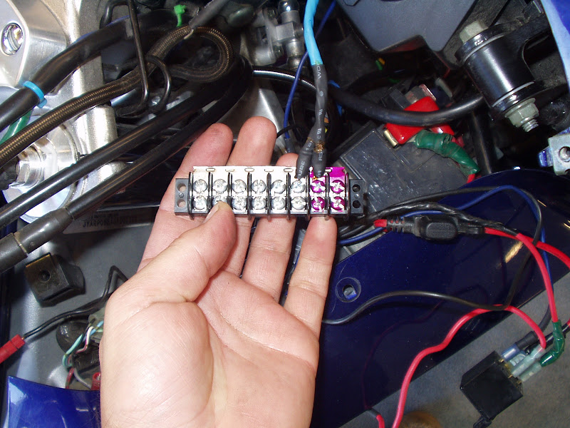
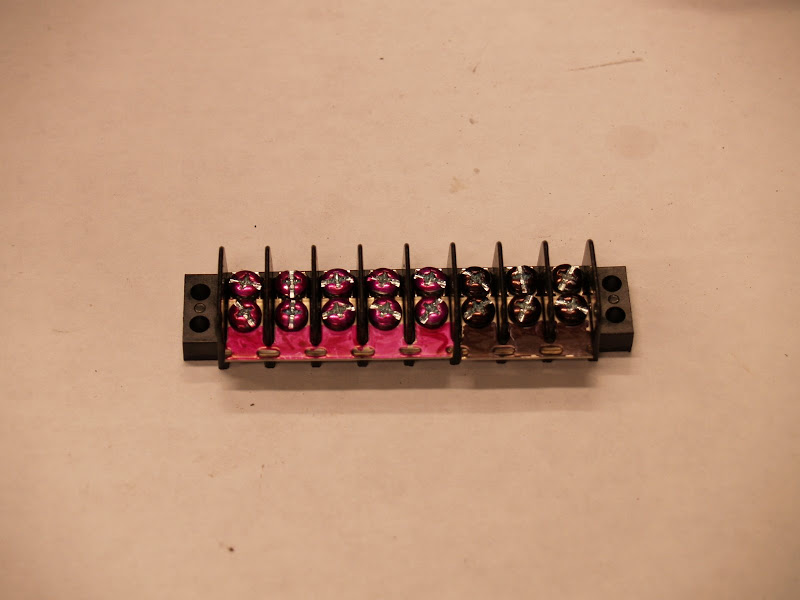
i plan to use a dual row barrier strip. what's positive and what's negative on the strip???? and where does the jumpers come in??? can somebody post a diagram including:

the battery, barrier strip, relay, farkles.

somebody shed some light. thanks.

 
This should help. I might have some pics of mine laying around on a CD from my previous HD. If needed, PM me and I'll see if I can find them as it was almost 5 years ago.

FJR Tech

 
A barrier strip is nothing but a row of screw terminals on each side with a little wall (the "barrier") down the center and between the screws. Each screw connects to the screw across the center wall from it, so if there are 6 screw on each side, you have six connections. One side is power, ground, switched power, and the other side is your devices.

Where positive or negative goes is up to you.

I have a barrier strip zip-stipped to the subframe behind the battery, under the upper faring, accessible when the D panel is removed. I connected battery to the first two screws, switched power to the second, and grounded the remainder.

It should go without saying that all power fed to the strip should be fused.

 
Last edited by a moderator:
Adding to what Wfooshee said, when you buy the barrier strip you can also pick up a metal strip that allows you to connect the entire length of the strip on one side together. That way the entire strip is either hot or ground, depending on which side of the battery you connect it to.

If you want to go the barrier strip route you will need one strip for positive and one for ground, or divide a single strip onto two isolated halves. Connect positive to one end and ground to the other end, then cut the metal connecting strip and make sure the positive end of the barrier strip is completely isolated from the ground end.

 
+1 to what Foosh wrote.

There're basically a couple of forms of barrier strip. There are the do-all blocks that have provisions for branching out to power multiple loads, have overload protection with breakers or fuses, and have ground provision. People tend to put these in the tail, just because the open area is there & it's easy to get to. Example: https://www.cyclenutz.com/products/electric...gative_bus.html

There are others that have portions, such as the widely used Centech (example: https://www.centechwire.com/catalog/cycles/ap1.shtml)

And then there are the plain-Janes like what your local Radio Shack offers for a few bucks. (Note at the bottom of the page is the jumper https://www.radioshack.com/product/index.js...ductId=2103229). A convenient place for these is on the hidden back wall of the glove box, as the battery side of the bike already is pretty packed.

Canyon Chasers had a good write up on the "how to" part of your question and it's still at https://www.canyonchasers.net/shop/generic/relay.php

 
A barrier strip is nothing but a row of screw terminals on each side with a little wall (the "barrier") down the center and between the screws. Each screw connects to the screw across the center wall from it, so if there are 6 screw on each side, you have six connections. One side is power, ground, switched power, and the other side is your devices.
Where positive or negative goes is up to you.

I have a barrier strip zip-stipped to the subframe behind the battery, under the upper faring, accessible when the D panel is removed. I connected battery to the first two screws, switched power to the second, and grounded the remainder.

It should go without saying that all power fed to the strip should be fused.
when installing a 8 position strip, how many amp fuse is ideal? bought a 30A blade type fuse

 
when installing a 8 position strip, how many amp fuse is ideal? bought a 30A blade type fuse
It's not based on positions on a strip, but the gauge of the wire used and the load you're expecting to put on the system. I would follow the suggestion of the FJRTech article otherwise.

 
+1 to what Foosh wrote.
There're basically a couple of forms of barrier strip. There are the do-all blocks that have provisions for branching out to power multiple loads, have overload protection with breakers or fuses, and have ground provision. People tend to put these in the tail, just because the open area is there & it's easy to get to. Example: https://www.cyclenutz.com/products/electric...gative_bus.html

There are others that have portions, such as the widely used Centech (example: https://www.centechwire.com/catalog/cycles/ap1.shtml)

And then there are the plain-Janes like what your local Radio Shack offers for a few bucks. (Note at the bottom of the page is the jumper https://www.radioshack.com/product/index.js...ductId=2103229). A convenient place for these is on the hidden back wall of the glove box, as the battery side of the bike already is pretty packed.

Canyon Chasers had a good write up on the "how to" part of your question and it's still at https://www.canyonchasers.net/shop/generic/relay.php
The Canyon Chasers' write up was excellent. Shows everything very clearly except I still don't understand the jumpers.

when installing a 8 position strip, how many amp fuse is ideal? bought a 30A blade type fuse
It's not based on positions on a strip, but the gauge of the wire used and the load you're expecting to put on the system. I would follow the suggestion of the FJRTech article otherwise.

Thanks. Think I'll run back and get a 25amp mini fuse holder and fuse.

 
sidebar question.

While i'm a fan of barrier strips because of simplicity, I"m wondering what might be some good ways to protect the terminals from extended exposure to water, salt, piss and all other things. Besides the obligatory dielectric grease, are there any kind of protectants that could be sprayed on for added protection?

I'm considering doing a very large heat-shrink-tubing when I'm done with the connections, but that sure takes away from easy access, it also might cause more harm than good if it ends up traping moisture inside(?).

any words of wisdom appreciated

 
Their placement in the fairing protects them. I did these in 2003 and they continue to work as intended.
https://www.fjr-tips.org/mods/pdb/pdb.html

Wrap each wire/connector in shrink wrap after soldering and Bob's your Uncle.
Always a treat to have Bob as your uncle. Never pass up that opportunity me thinks. LOL

Ya, I agree placement will is a big factor. I've got a strip a few years old and it's showing mild corrosion, I was thinking how I might better protect the 2nd time around, I know I'll be paying a bit more attention to location as well as grease.

Nice to see your pics and such ....For me the grooviest thing about barrier stips is that you have such flexibility on where you place them ...based on needs personal preference etc.

thanks

 
Last edited by a moderator:
Their placement in the fairing protects them. I did these in 2003 and they continue to work as intended.
https://www.fjr-tips.org/mods/pdb/pdb.html

Wrap each wire/connector in shrink wrap after soldering and Bob's your Uncle.
Always a treat to have Bob as your uncle. Never pass up that opportunity me thinks. LOL

Ya, I agree placement will is a big factor. I've got a strip a few years old and it's showing mild corrosion, I was thinking how I might better protect the 2nd time around, I know I'll be paying a bit more attention to location as well as grease.

Nice to see your pics and such ....For me the grooviest thing about barrier stips is that you have such flexibility on where you place them ...based on needs personal preference etc.

thanks
what determines placement of jumpers on the barrier strip?? i still dont get the principal of the jumper. how are they placed????

 
what determines placement of jumpers on the barrier strip?? i still dont get the principal of the jumper. how are they placed????
Styles may vary, but a typical barrier strip with (the uninstalled) jumper to the right shown here:

TE-085-000.gif


Note: This particular style of jumper is designed to be cut down if you don't want to "jump" all of the terminals.

There are different styles, I personally prefer single jumpers vs this style ....but variety is the spice of life they say.

i have seen pictures of both and i have both in my possession. identification of each is not the issue here. the problem i am having is how do you determine placement of the jumper? how does it work and what is the principal behind them??????

 
[quote name='RenoJohn' post='727986' date='Apr 19 2010, 03:38 i have seen pictures of both and i have both in my possession. identification of each is not the issue here. the problem i am having is how do you determine placement of the jumper? how does it work and what is the principal behind them??????
It's up to you. You want 8 different terminals with different function then no jumper. Wire it at one side and the other screw picks up that voltage only. You want like 15 hot powered screws then wire one screw with input, install the jumper and use any of the other 15.

Or, an example below is I wanted 3 powered taps on all the time and 11 when the bike was on.. I cut the jumper, took a red sharipie to color the permanently hot ones, and installed. You can't see it, but there's an air gap between what is now two separate jumpers. They're not rocket science...just basic electricity......things connected by metal will flow electricity. Things not connected by metal won't.

P1010096.JPG


Or another where I run part hot and part as a grounding strip. You can see the air gap of the cut jumper. I trimmed it in two places. Again sharpie color just helps me remember.

MW061030.JPG


Last edited by a moderator:
took a red sharipie to color the permanently hot ones,
LOL Exactly what I did, but fingernail polish instead of sharpie. ...but that's just how I roll.

BTW: Nice pictures.

This go around I'm going to use a couple of smaller barrier stripS for "hot" (key on, key off etc) and one common one for negative. In other words a few small barrier strips vs one large. For me this will make for easier placement.

 
In trying to clear up continuing confusion, I've borrowed Iggy's picture.

Completely aside from the jumpers, keep in mind that the numbered pairs are ALWAYS connected. 1 goes to 1, 2 goes to 2, 3 goes to 3, etc. So whatever power source you connect to the top #1 screw is available at the bottom #1 screw. That serves the purpose of the strip: a convenient place to attach connections.

P1010096.JPG


The jumper strips basically make a whole set of screws the same thing. In Iggy's #1 to #6 are ground, with a negative cable connected to the top #6, and all the other top screws 1 through 6 connected by the jumper strip. You can then connect any device to ground by connecting its black wire to any of the bottom screws 1 through 6. He connected 12 volts to the top #7, and 7 and 8 are connected together by the jumper strip. He cut the jumper between 6 and 7, making it 2 separate pieces. Any accessories can now get power by connecting their power wires to the bottom screw, either #7 or #8. As pictured, the supply connections are at the top, the accessories would be connected at the bottom.

I did similar with my strip but made three sections: ground, always 12 volts, and switched 12 volts.

 
Last edited by a moderator:
In trying to clear up continuing confusion, I've borrowed Iggy's picture.
Completely aside from the jumpers, keep in mind that the numbered pairs are ALWAYS connected. 1 goes to 1, 2 goes to 2, 3 goes to 3, etc. So whatever power source you connect to the top #1 screw is available at the bottom #1 screw. That serves the purpose of the strip: a convenient place to attach connections.

P1010096.JPG


The jumper strips basically make a whole set of screws the same thing. In Iggy's #1 to #6 are ground, with a negative cable connected to the top #6, and all the other top screws 1 through 6 connected by the jumper strip. You can then connect any device to ground by connecting its black wire to any of the bottom screws 1 through 6. He connected 12 volts to the top #7, and 7 and 8 are connected together by the jumper strip. He cut the jumper between 6 and 7, making it 2 separate pieces. Any accessories can no get power by connecting their power wires to the bottom screw, either #7 or #8. As pictured, the supply connections are at the top, the accessories would be connected at the bottom.

I did similar with my strip but made three sections: ground, always 12 volts, and switched 12 volts.

I am now enlightened and see the way of the power strip! Man, should have paid more attention in class. Thanks everyone!!

 
Top