CO2 Sensor Connection Plug

Yamaha FJR Motorcycle Forum

Help Support Yamaha FJR Motorcycle Forum:

This site may earn a commission from merchant affiliate links, including eBay, Amazon, and others.

Fullchat

Well-known member
Joined
Nov 11, 2010
Messages
54
Reaction score
1
Location
East Yorkshire, England
I'm just in the process of fitting a Power Commander 5 in the hope of smoothing things out a bit. Everything fitted but now have to disconnect the CO2 sensor. To save me stripping off the side panel can anyone tell me where the connector plug is. I have a suspicion its up near No4 injector.

 
Last edited by a moderator:
On the right side of the motorcycle, look at the exhaust system near the right foot peg for an item screwed into the exhaust system, that would be the O2 sensor (less the C), it will have wires coming out of the sensor. Follow the wires up and the first connector you find that the O2 sensor wires go into is the connector you want to unplug
smile.png
You are right it will be on the #4 injector area but a bit down from there.

 
Last edited by a moderator:
O2 sensor is on the right side of the fuel rail . throttle bodies under the tank. You'll see the cable running down to the sensor on the exhaust pipe

Edit - Bruced!

 
Last edited by a moderator:
Thanks so far. I can see the sensor in the exhaust but it is difficullt to follow the wire without taking the side panel off. Tank is already removed as part of the PC fitting process.

 
Your Gen II has a 3 wire sensor that goes to a triangle shaped connector. Some times it helps to take one hand and hold wires up by the injector and take the other hand and gently pull on the wire down by the sensor and see what moves. Generally you can zero in on the connector this way.

 
Your Gen II has a 3 wire sensor that goes to a triangle shaped connector. Some times it helps to take one hand and hold wires up by the injector and take the other hand and gently pull on the wire down by the sensor and see what moves. Generally you can zero in on the connector this way.
It's not often I would question anything ionbeam wrote, but ...

I think the 3-wire sensor and triangular connector belong to the cylinder identification sensor.

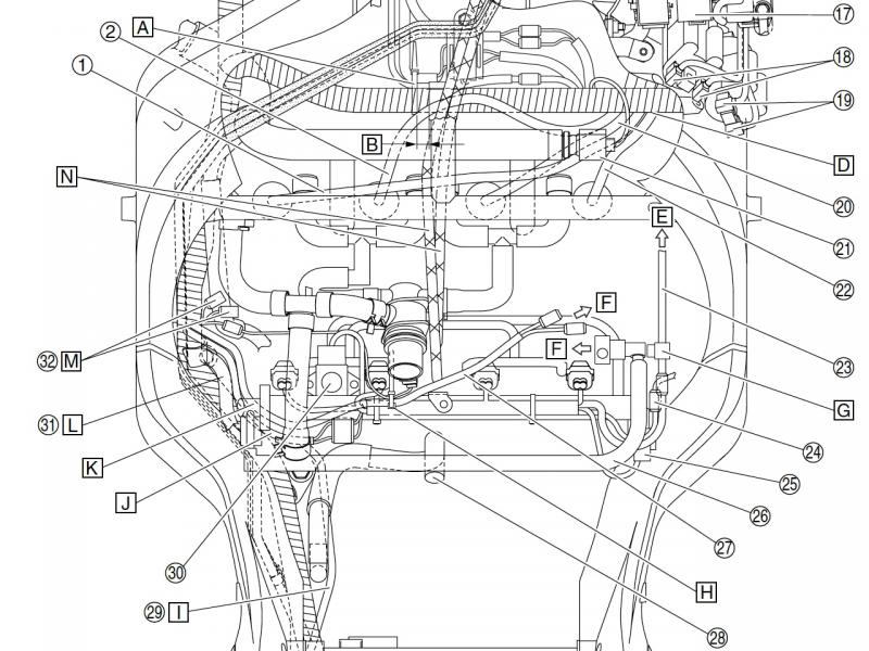
The O2 sensor has 4 wires, going to a square four-pin connector, colours of wires: black, black/blue, red/blue, grey/white. At least, that's what my '06 wiring diagram shows.

The connector is item number 24 in the cable routing diagram below:

1_O2SensConn24.jpg


Last edited by a moderator:
Thanks Mc. I did wonder as the white 3 pin connector goes in direction E over the top of the engine to the front where as the (black) connector you mention does drop down the side of the engine towards the CO2 sensor.

 
Last edited by a moderator:
Job done. Undid some of the side panel bolts which allowed me to pull outwards and gain some wriggle room and used the wire tugging method to trace its route. Appears it is the black pug as suggested by Mc. Anyway that's the one that has been disconnected
rolleyes.gif
. Thanks everyone for their responses.

 
Your Gen II has a 3 wire sensor that goes to a triangle shaped connector...
It's not often I would question anything ionbeam wrote, but ...I think the 3-wire sensor and triangular connector belong to the cylinder identification sensor...
Thanks for the correction. My info was from my '06 FSM electrical schematic which did show the triangular connector. My '04 manual has some errors inconsistencies too.

Glad the connector was found and neutralized.

 
Last edited by a moderator:
Your Gen II has a 3 wire sensor that goes to a triangle shaped connector...
It's not often I would question anything ionbeam wrote, but ...I think the 3-wire sensor and triangular connector belong to the cylinder identification sensor...
Thanks for the correction. My info was from my '06 FSM electrical schematic which did show the triangular connector. My '04 manual has some errors inconsistencies too.

Glad the connector was found and neutralized.
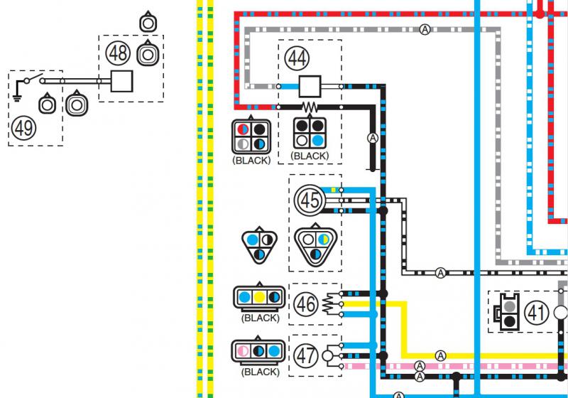
I am a little surprised, these snippets from the manual I use (please excuse the sizing, done in a hurry):

1_sensors_schemtic.jpg


Key:


Obviously somthin' ain't right, my manual has different numbering for the sensors but it looks like I simply got it wrong.

 
Obviously somthin' ain't right, my manual has different numbering for the sensors but it looks like I simply got it wrong.
I think you might have been looking at the second page of keys that refers to the AE's schematic, that has totally different numbers.
He's milking the moment :punk:
ManMilkingCow.jpg
 
Last edited by a moderator:
Top