Cam Chain Help Needed

Yamaha FJR Motorcycle Forum

Help Support Yamaha FJR Motorcycle Forum:

This site may earn a commission from merchant affiliate links, including eBay, Amazon, and others.

NorthernRider

Member
Joined
Aug 31, 2014
Messages
12
Reaction score
0
Location
Roseau, MN
I am a fairly new owner of an 05 FJR with around 32,000 miles on. The previous owner was the second owner and was uncertain of the maintenance history. Being the kind of guy that likes to know where a bike is at mechanically before putting on a bunch of miles I started in on the usual maintenance items which including checking the valves. One exhaust valve was measuring .005, cam comes loose (zip tied chain to both cams), new shim goes in, torque cam back down, release tensioner, rotate and things look off. Assuming the chain jumped a tooth I set off to fix the problem, problem is I can't seem to get it back to how the service manual shows. To add to the misery I am trying to do this with the engine in the frame.

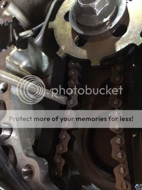
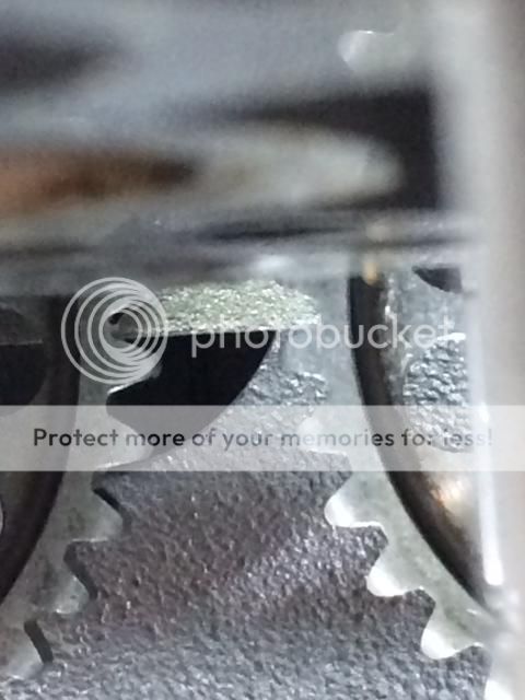
Engine at TDC on #1 cylinder

photo1-1.jpg


Intake cam appears aligned

photo2-1.jpg


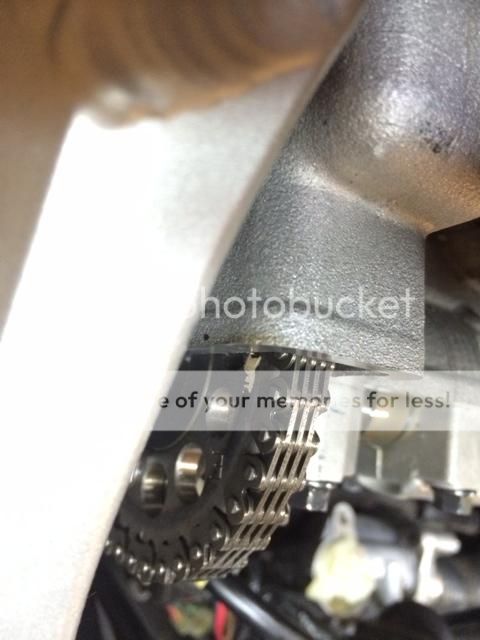
but also one tooth off compared to the exhaust

photo3-1.jpg


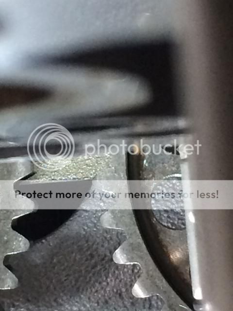
Teeth clearly not aligned

photo4-1.jpg


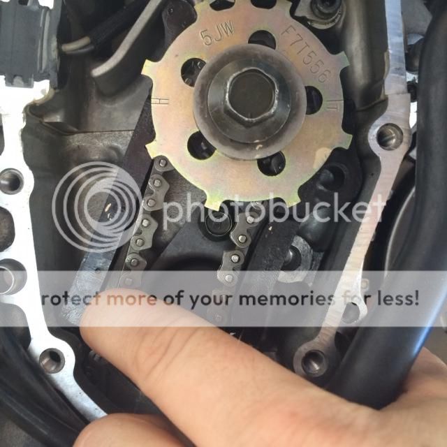
If I rotate a little further it past TDC

photo1.jpg


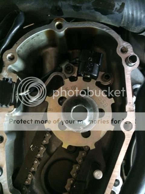
the cams align with one another.

photo2.jpg


photo3.jpg


photo4.jpg


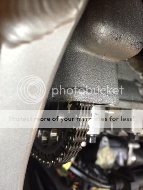
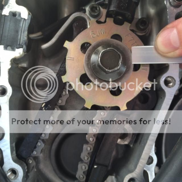
If I set the cams first, put chain on exhaust cam and then around crank sprocket there is always a small amount of slack. This could be the source of my issues but I can not get the chain that apparent one tooth tighter than it needs to be. Seems like no matter what what I try I arrive at the same state of alignment. I'm about ready to throw in the towel and my riding season is drawing to a close. Any sage advice out there on what I am doing wrong?

 
I went through this on my '05 a few months ago and I had to fool with it a while to get the timing correct. I'm not sure what you're looking for on the cam sprockets but I used the punch marks on both cams (@ #4 cyl.) and aligned them with right facing arrows on the cam bearing caps on both cams (my Yam shop manual states this too). The REAL issue was that the cam chain kept slipping off the crankshaft sprocket due to the CCT being retracted. Besides having the chain tie-wrapped to the exhaust cam sprocket, I also had to tie-wrap it down below at the crank to keep the chain tight and engaged with the crank thereby ensuring the timing and allowing there to be enough slack up top to get the @$!#! chain over the intake sprocket. Going on memory here but that's what I remember. Don't give up! I'm sure others will speak up and help you out!

Regards,

Brendan

 
Last edited by a moderator:
Thanks Brendan, I'll keep at it and have the girl on the road yet! Here is a picture of the amount of slack in the chain from the exhaust cam down to the crank gear. I've read that there needs to be no slack in this run of chain but there isn't enough slack to get it to the next tooth either.

photo.jpg


Is this with the Cam Chain Tensioner (CCT) fully retracted?

If yes, take a flashlight and closely inspect the bottom sprocket to ensure the chain is engaged normally. It's very easy to miss!

Mr. BR

 
I think you are over-thinking this a bit. Slack in the chain only depends on which way you rotate the the crank. Rotate it clockwise and the forward part of the chain will have no slack. Rotate it the other way and there will be a slight amount of slack.

There are lots of good threads around here with tons of technical help and photos.

From your photos, it seems the intake cam is off by one tooth. Which if you zip-tied, I don't how that happened.

The only way to get it in time is to use the dots on the cams which requires the use of a mirror for the forward exhaust cam, or the timing marks on the cam sprockets you show photos for which also require the use of a good dental mirror and a flashlight, and maybe even a straight-edge to make sure it is right.

Unfortunately I am not at home where I have some good photos, but RadioHowie has an excellent reference thread here: https://www.fjrforum.com/forum/index.php?showtopic=122970

 
Last edited by a moderator:
https://i5.photobucket.com/albums/y161/radiohowie/Cam%20Chain%20Replacement/chain03.jpg

It's very easy to check for the correct position of each camshaft using a simple right triangle or any object with two flat sides with a 90 degree angle between.

Looking at the above photo you can see the pip on each camshaft lobe and how it should be aligned with the vertical line on the adjacent camshaft cap. The cap has a flat surface on both sides of the vertical line which is perpendicular to the the camshaft.

Just slide one side of your right triangle sideways up against the the vertical line on the cap with the other side of the triangle extending horizontally out over the camshaft lobe and its pip. With the 90 degree point of the triangle against the vertical line the edge of the triangle will highlight where the pip is located. If the camshaft is oriented correctly you'll see the pip lined up closely adjacent to the edge of the triangle. With the triangle positioned down low on the camshaft lobe you'll have no problem seeing the pip's position accurately.

 
Thanks for the advice everyone. I tried out the approach of lining up the cams using a straight edge off the cam caps.

Intake looks centered

photo1-2.jpg
E

Exhaust cam also lined up (sorry couldn't get focused so its a tad blurry). Marks on the side of the cam sprockets along with the teeth also aligned nicely.

photo2-2.jpg


Put the chain on the exhaust cam and around the crank sprocket (set at TDC) I continue to get some amount of slack.
photo3-2.jpg


If I rotate clockwise to take up the slack I end up past TDC.

photo4-2.jpg


Rotate around back to TDC and I end up in the same one tooth off scenario. For those that have done this job before, do I just need to try harder to get to the zero slack state between exhaust cam and crank sprocket? Could chain stretch be a factor or am I just missing the boat altogether in my approach to getting this thing back together? Thanks everyone.

 
Hi,

When I replaced my chain, I set the chain over the exhaust cam first and only rotated the crank clockwise.

Never reverse the crank, if it goes past the mark, keep rotating clockwise and set it right.

Once the exhaust cam is set right with #1 at TDC, then align the inlet cam.

Had to go through the full procedure as my mate moved the crank backwards, only a fraction and the Hyvo slipped 1 tooth

 
That front side of the chain (opposite the tensioner) has too much slack in your pic to time the cams to spec. I have heard of people saying to set the cams one tooth forward with the tensioner out, and when the chain tightens under tension, the timing of the cams backs them into place. But with a slack chain, you want the cams to be ahead of where they belong. When you put in the tensioner, then apply a little turn to the crankshaft. It will turn just a bit before it starts pulling the cams as it takes up that front slack. The tensioner is not strong enough to pull the cams backward and tension the front side of the chain. The timing isn't finalized until your turn the crank far enough to tighten that.

When I just pulled my exhaust cam a couple days ago, I removed the "hidden" bolt of the sprocket first, then turned to the timing marks. I zip-tied the chain to both sprockets, then zip-tied the bottom just above the dowel on the left, and as close to the crank as I could get on the right. Backed the tensioner out and got to work. I know you intended that, just missed the bottom part of the chain.

 
Last edited by a moderator:
There are 38 teeth on the camshaft sprockets and 19 teeth on the crankshaft sprocket.

19 teeth = 18 spaces between teeth = 20 degrees of rotation between adjacent teeth

38 teeth = 37 spaces between teeth = 9.73 degrees between teeth

An error of 9.73 degrees would be very noticeable using the straight edge evaluation technique.

The diameter of the camshaft is 25 mm at the pip's location.

9.73 degrees of error = 2.12 mm of circumference error (distance around circumference of camshaft),

I'm confident you can recognize that much error using the 90 degree straight edge.

I don't know the diameter of a pip but I doubt it's much bigger than 2 mm. You can easily measure the diameter of the intake cam pip. Let us know what you find.

 
When using the straight edge on the exhaust cam I'd recommend positioning it on the forward or front side of the pip. That way you don't have to look over the top of the straight edge to see the pip. You should be able to see everything more clearly with that orientation.

 
In your last photo the left side damper isn't in the right position.The pin isn't in the hole.Put the damper on its place with the pin in and then check it again.Also from your photo not seems that is one tooth out..Is out a little but not one tooth..Install the CCT and the damper on its right place and check it again.If you can't see any difference then set the cams one tooth forward as wfooshee said and check again.

 
Last edited by a moderator:
Yeah, what Mihalis said. Your intake-side chain guide/slipper is NOT in the correct position, leaving all kinds of slack in the chain.

The timing must be done with everything in its correct place, i.e., the crank sprocket lined up correctly (which you appear to have done correctly). But the the chain slipper not anchored correctly, you'll never get the timing set right.

You really need to start from scratch. And since you SHOULD start from scratch, I'd recommend taking the cams out and transferring the timing marks from the front of the cam sprockets to the back side, either with a ground-in mark, or at least with a daub of white paint, so you don't have to rely on trying to see the "impossible-to-see" marks on the front of the cams.

The important thing is to take your time, make sure the chain slippers/guides are in their correct positions, and don't try to time the cams with ANY slack in the chain.

 
I am happy to report that my cams are properly timed with the crank now. Took Howie's advice and pulled the cams. Getting rid of ALL the slack between the exhaust cam and crank sprocket was the difference maker. Thanks everyone for the help!!!

 
I am happy to report that my cams are properly timed with the crank now. Took Howie's advice and pulled the cams. Getting rid of ALL the slack between the exhaust cam and crank sprocket was the difference maker. Thanks everyone for the help!!!
So, how does it run? Have you done a TBS?

 
In your last photo the left side damper isn't in the right position.The pin isn't in the hole.Put the damper on its place with the pin in and then check it again.Also from your photo not seems that is one tooth out..Is out a little but not one tooth..Install the CCT and the damper on its right place and check it again.If you can't see any difference then set the cams one tooth forward as wfooshee said and check again.
Well spotted Mihalis, everybody else was off on a wild goose chase..................

 
In your last photo the left side damper isn't in the right position.The pin isn't in the hole.Put the damper on its place with the pin in and then check it again.Also from your photo not seems that is one tooth out..Is out a little but not one tooth..Install the CCT and the damper on its right place and check it again.If you can't see any difference then set the cams one tooth forward as wfooshee said and check again.
Nice catch!

 
Top