FJR Ignition current draw

Yamaha FJR Motorcycle Forum

Help Support Yamaha FJR Motorcycle Forum:

This site may earn a commission from merchant affiliate links, including eBay, Amazon, and others.

mcatrophy

Privileged to ride a 2018 FJR1300AS
Joined
Aug 25, 2006
Messages
4,332
Reaction score
1,824
Location
Derby, UK
To satisfy my curiosity, I decided to measure the current draw under various non-running conditions (how long will the battery hold up with the ignition on?), this on my 2014 FJR1300AS (it would be the AE in the USA, and has the ES suspension).

So, I hooked up a meter in series with the negative connection (without ever breaking the connection so no trips were lost), pointed my camera (mostly set to movie) at the meter, and did a few tests.

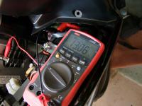
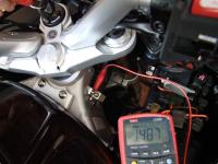
Firstly, the battery voltage after the bike had sat for over a day: 13.06V

(Click on image for larger view)


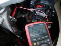
Ignition off: <0.01mA (<10uA)


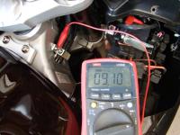
Kill switch off (engine could run):

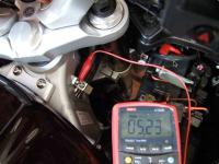
Turn ignition on, initial current 9.1A, dropping to ~ 4A after the fuel pump stops.


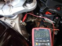
Turn off the ignition, kill switch set to On (fuel pumps won't run), now turn on the ignition:

~ 5.2A dropping to ~ 4A after a second or so.
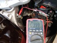
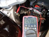
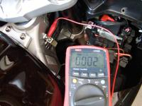


Ignition off:

0.47A then down to 0.002A (the higher current is while it's saying "Goodbye" [how Japanese]).


And with the ignition switch in the "Park" position (mine is a '14 with the LED front side-lights):

~ 1.5A


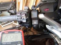
Finally, because I have my heated vest controller/voltmeter, I measured its current:

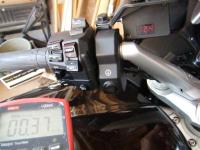
128mA (varying a little with the display segments) down to 37mA as the display changes from bright to dim.


Just thought it might be of interest to see how long the battery might hold up for if the engine isn't running, my guesstimates* to half capacity:

  • Ignition left on (NO HEADLIGHTS), 4 amps, say 50 minutes;
  • Parking lights left on, 1.5A, say 3:30 hours;
  • With headlights: (4A plus say 2 x 4.5A = 13A) say 12 minutes.
* I am assuming the battery has a Peukert number of 1.2, and extrapolating from the 1.2 curve in the graph below:

PbAcidCalacity.jpg


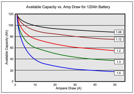
Capacity Current Multiplier at current Time to half 12 4 0.57 00:51 12 1.5 0.87 03:28 12 13 0.45 00:12

(Reference: https://batteryuniversity.com/learn/article/calculating_the_battery_runtime).


Last edited by a moderator:
<Double post, deleted>

 
Last edited by a moderator:
Interesting info, thanks.

The double post, however, may get your Grammar Police badge withdrawn. Higher standard and all.....

 
Last edited by a moderator:
Interesting info, Thanks.

Have just been researching how I'm going to circumventing my key switch with a wirelessly activated relay and was wondering about how it would be easy to forget the on. Bottom line here is don't, eh?
rolleyes.gif


So I've been contemplating a timeout on the relay trigger. Probably a good idea, but haven't given any thought as to what signal to use to tell me the engine isn't running. Hmmmm...

 
I made some of these measurements a couple of months ago on a Gen 1 '05. I was trying to work out how long the bike could be left with the ignition on before it would struggle to start. The answer is ... Not very long.

K ON E OFF ,,,, Initial 7.5 Amps falling to 3.5 Amps when fuel pump stops.

What I'd like to measure is the current draw with the engine running and everything off except the low beams. With a decently charged battery that would give a reasonably accurate estimate of the power left to operate "farkles" safely.

My meter will only handle 10 Amps, so I'm thinking I would have to connect it to the battery terminal and the positive lead, strt the engine and then remove the positive lead from the battery allowing the current to flow through the meter.

Does that sound like a plan, or would a clamp-on ammeter be better?

 
Last edited by a moderator:
Interesting info, Thanks.
Have just been researching how I'm going to circumventing my key switch with a wirelessly activated relay and was wondering about how it would be easy to forget the on. Bottom line here is don't, eh? :rolleyes:

So I've been contemplating a timeout on the relay trigger. Probably a good idea, but haven't given any thought as to what signal to use to tell me the engine isn't running. Hmmmm...
The crude method would be to detect AC on one of the coil feeds. I don't know your technical level, but simply a capacitor one end connected to the switched coil primary, a diode, negative to ground, positive to the other end of the capacitor, a second diode, negative to that junction, positive to a resistor whose other end goes to ground, and a capacitor in parallel with that resistor.
If suitable values are chosen, with the engine not running, ignition on or not, there would be no voltage across the resistor. With the engine running, there would be a voltage across the resistor. A bit of original design to determine sensible values and a little experimentation would be needed, but the principal is good.

There may well be more sophisticated methods, but that will work.

 
Last edited by a moderator:
I made some of these measurements a couple of months ago on a Gen 1 '05. I was trying to work out how long the bike could be left with the ignition on before it would struggle to start. The answer is ... Not very long.
K ON E OFF ,,,, Initial 7.5 Amps falling to 3.5 Amps when fuel pump stops.

What I'd like to measure is the current draw with the engine running and everything off except the low beams. With a decently charged battery that would give a reasonably accurate estimate of the power left to operate "farkles" safely.

My meter will only handle 10 Amps, so I'm thinking I would have to connect it to the battery terminal and the positive lead, strt the engine and then remove the positive lead from the battery allowing the current to flow through the meter.

Does that sound like a plan, or would a clamp-on ammeter be better?
Your biggest problem would be the potential current either charging or discharging the battery exceeding the 10 amp range of your meter. Most meters are fused on their high current range. That should protect the meter, and probably would not harm the bike, although it may cause the engine to stop running (no big deal).
If you look at my second picture in my first post above, you can see I use the negative terminal of the battery to do near enough what you propose, it's much easier to access than the positive terminal (at least on a Gen II or Gen III). Simply hold the negative cable (with the meter clip attached) on to the battery terminal while you start the bike, wait 20 seconds or so for the initial charge current to reduce, then lift up the cable (still with the meter clip attached). On all of my FJRs (two Gen IIs and one Gen III), at cold tick-over, the battery voltage would rise to around 14 within 15 seconds or so, when the charging current would be quite low.

 
I'm one with very little electrical knowledge. My GPS is hot wired to the battery. If I do not disconnect it will it eventually discharge the battery? Let's assume the GPS is partially or fully charged when I shut down the bike. The reason I hot wired it is so I can turn off the ignition and not shut down the GPS. When not using the bike I remove the GPS. I'm curious about the discharge effect over a lunch break and etc.

 
If your GPS is off, it will only draw long enough to charge. If you leave it on, it will run your battery down overnight. Maybe 12-14 hours. Leaving it on at lunch is not a big deal, unless it's a 13 hour lunch. Haha...

 
Good info Mcat. Thanks for taking the time to measure. I bet that initial current at 9.1A just about reached the max of your meter?

I think it was mentioned above, but what are your thoughts on simply using a clamp-around DC amp meter for these measurements?

mfppW5gtR1XWeA4GC_wUyeg.jpg


I'm one with very little electrical knowledge. My GPS is hot wired to the battery. If I do not disconnect it will it eventually discharge the battery? Let's assume the GPS is partially or fully charged when I shut down the bike. The reason I hot wired it is so I can turn off the ignition and not shut down the GPS. When not using the bike I remove the GPS. I'm curious about the discharge effect over a lunch break and etc.
Zumo and the StreetPilot 2XXX series switch off completely with their "OFF" buttons. Most other Garmins do not, they draw 1/2 Amp when apparently switched off.

 
...I bet that initial current at 9.1A just about reached the max of your meter?
I think it was mentioned above, but what are your thoughts on simply using a clamp-around DC amp meter for these measurements?
Clamp on amp meters are far and away easier to use than series amp meters as long as you don't need 0.001 accuracy. Digital meters which have a series meter lead hookup tend to have 10A as the peak scale though I do have a meter that does 20A. These high current ranges are separately fused, buy a box of fuses
wink.png
Clamp on amp probes won't blow a fuse if the reading goes over scale.

I have a couple of useful but hard to find AC/DC clamp on amp meters. They have DC current ranges of 40A and 400A for one and 20A to 2000A on the other meter. Most useful is the Peak-Hold button which locks the highest amp reading no matter how fleeting the measurement reading was, 'cause the meter display flickers fast as things click, whirr and spin. These days you can find an adequate clamp on amp meter starting in the $50 range. I've tested my meters on a test bench and find them to be adequately accurate and not too disturbed by electrical 'noise' such as would be produced by the spark system. One meter does both clamp on amps as well as conventional DMM functions with meter leads.

 
Last edited by a moderator:
Good info Mcat. Thanks for taking the time to measure. I bet that initial current at 9.1A just about reached the max of your meter?
I think it was mentioned above, but what are your thoughts on simply using a clamp-around DC amp meter for these measurements?

...
Meter is a 10amp, but I video-recorded its display during each condition to look for extremes. While it could have missed a very short current spike, I saw no indication of anything over the maximum I quoted.
As for clamp-on meters, I've no experience with DC ones, but I certainly bow to ionbeam's opinion.

One obvious advantage of the clamp meter (besides ease of "connection") is there is no voltage drop during a static measurement (arguably there is a little voltage drop during rapidly changing current - that is an assumption on my part, and probably won't affect these types of measurement).

With a conventional meter (analogue or digital) there is inevitable voltage drop both within the meter and in all the leads and connections, which will have an effect - albeit probably not significant for these purposes (in these measurements, who cares if it's 3.9 amps or 4.1?).

 
Last edited by a moderator:

Latest posts

Top