Gen II Accessory Wiring for grips and gps

Yamaha FJR Motorcycle Forum

Help Support Yamaha FJR Motorcycle Forum:

This site may earn a commission from merchant affiliate links, including eBay, Amazon, and others.

Kelvininin

Well-known member
Joined
Jan 6, 2016
Messages
154
Reaction score
66
Location
Corcoran MN
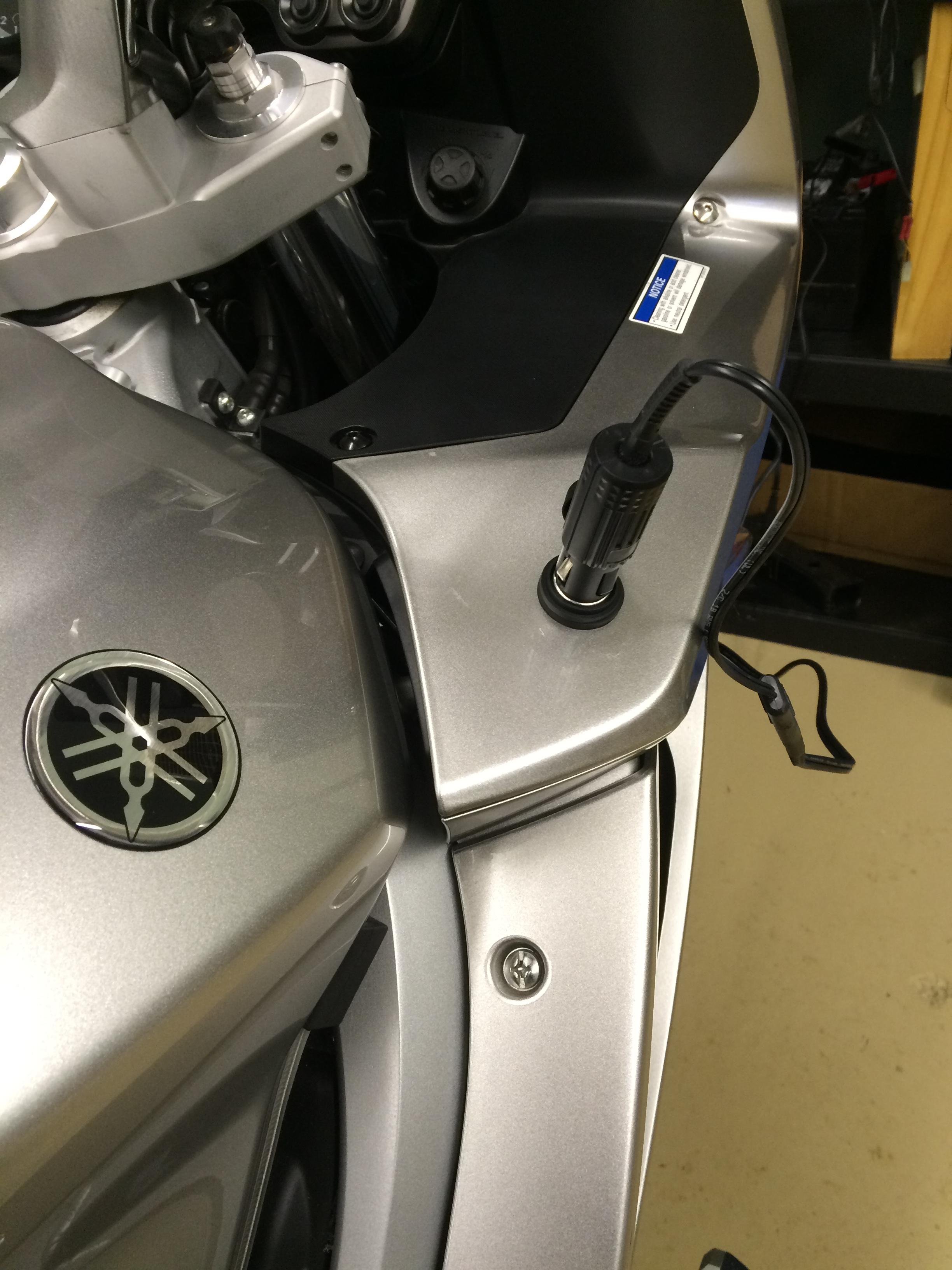
I have begun farkling my FJR. I am getting ready to install my zumo 660 and some oxford heated grips. I would like to use the exsisting accessory wiring for the grips and GPS. For the GPS I will take into power for the cig lighter port in the glove box. For the grips I would like to use the Yamaha existing wiring.

I understand there are two connectors associated with the Yamaha heated grips, a white and blue connector, both are two pin. The white connector is a communication connector, the blue is power?

I put a meter to the blue connector and got nothing. Is the power associated with the head light, so the connector will not see power until the engine is running?

Thanks!

 
Last edited by a moderator:
Did your bike come with the original heated grips, ie with the heater controller on the LHS of the dash, the rotary switch ?

You will need the Yamaha controller.

The ECU controls power to the grips, power is not on all the time. Maybe depends on ECU voltage detection ????

Also Yamaha's grips are wired in series, ie 6 volts per grip & not parallel 12 volt.

 
Last edited by a moderator:
The two heated grip controller connectors are shown below, picture taken with the fairing off:

(click on image for larger view)


The blue connector has two wires, green and red/black. The green has headlamp-switched power, the red/black connects to the left-hand grip.

The white connector has two wires, black and green/white. The black connects to ground, the green/white to the ECU, presumably used to tell the controller to reduce power if the battery voltage is too low.

Original wiring has the right-hand grip warmer connected directly to 12V via the signalling fuse, this is where the OEM installation draws its power. The other right grip wire connect across to, and in series with, the left grip, the left grip then connects to the controller via the red/black wire. The original controller switches the red/black wire to ground to complete the circuit.

My advice for a simple non-OEM installation is to use the green wire in the blue connector for your power source - this comes from the headlight circuit that can easily provide the extra power, and ensures that no power is sent to the grips unless your motor is running*. Use the black wire of the white connector for the ground - this keeps the installation neat. However, it may be better to find a separate ground return to the battery if there's any doubt about your grounding loom and its potentially troublesome "spider" connectors.

For the GPS, by all means use the power to the socket in the glovebox. It's not much use for anything else with its 3 amp fused circuit.

*Assumes you don't stop the motor with stop switch or whatever that will leave the headlights on.

 
Last edited by a moderator:
Thanks for the fantastic information!! I am still waiting for my service manual, so I am trying to get by as is.

My bike does not have the yamaha heated grips. I picked up the Oxford adventure grips.

I never understood the low amperage rating of the Yamaha 12v port. Ok for GPS, and a cell phone not much else, including an air compressor. So I installed this, fused direct run to the battery, also good for the battery tender. I had the powerlet port sitting around from a previous project, they make for a nice clean install but are spendy.

Mftvv49.jpg


Top