I am hesitant to correct Dr. Ionbeam, but I think you really want the
TPI A256 rather than the A250. If I read the spec's right, the A250 is only good for AC while the A256 goes both ways.

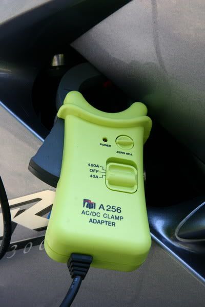
In another related thread I posted a picture of my amp probe which is indeed a TPI A256 and not the A250. Here is the picture of my amp probe --
OK, wading thru your data, it looks like the 6 ohms between the RR and battery is pretty significant to me. If you find those 6 ohms you'll find your lost voltage.The reason the voltage difference is low when nothing is running is you aren't drawing any current through that resistance. As soon as you start the bike and add a load you start to draw current which results in a voltage drop across the resistance. You should be able to find that resistance with the ohm meter, and the bike not running.
Ideally, to get an accurate resistance reading there should be no voltage on the wire (the battery should be disconnected). Also, it is difficult for someone that isn't an electrical type to make accurate resistance measurements below 20 Ω because of lead resistance and the necessity of good contact. When people tell me they ohmed their stator and it measured 0.2 Ω per the FSM I get a little worried. Take any standard DMM, set it to the lowest ohm scale and touch the leads together, the meter will typically read the lead resistance of 0.2 to 0.6 ohms which is greater than the value they are trying to measure.Off line I sent Dcarver a structured list of tests to perform which included a voltage drop test from the R/R to the battery going through each item in the path of the positive and negative side. We are trying to track down less than one missing volt, which isn't much.
Yup, fully understood. And that offline info (after he copied me in on your PMs
) is what led me to believe the resistance is real and probably important. He be dropping milli-volts all over the place.For anyone (trying to) follow along, this is not a life or death crisis here by any means. Nothing to get your panties too tightly twisted about. DC, being an anal retentive type A guy like me (yet he does have a soft creative side to him
) is worried that his battery charging system is not "quite up to snuff." He is not in danger of being stuck on the side of the road like some poor BMW riding slob with a flaming final drive.
But when people are fully in-tune with their bikes they know that, in general, a difference noticed is not a good thing in the long term.In search of missing millivolts continues...