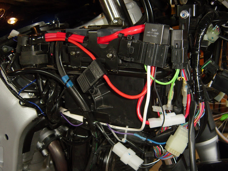
There's something I wish I would have done...as you feed the wires through the loom, label them so you know what they are. Was a pain figuring it out after I ran everything through. Labels also work good if you're sending extra wires through for future farkles.
If anyone wants to do a tutorial, here's some snippets of stuff I sent to people...
https://www.canyonchasers.net/shop/generic/...agram-final.jpg
Supplies (assuming you have the Blue Seas box already):
Approx 10’ Black and 10’ Red 10ga wire
Approx 1’ 14ga wire (or more depending on distance from power source to relay)
2 10ga ring (large) connectors (for battery)
Inline 30W fuse
2 10ga wire splice connectors (for inline fuse)
2 10ga ring connectors (for Blue Seas block)
1 14ga tap-in connector (for power source to relay)
30amp 12v relay
4 blade connectors for relay
14ga Black and Red wire for connection to relay and accessories
14ga ring connectors (for accessories to Blue Seas block)
Approx 6’ wire loom
ATO or ATC type fuses (amperage depends on accessories)
Velcro for connecting Blue seas box to inner fender
(keep in mind, I have an '04...most of the stuff should be universal)
For my wires, I used red for +, black for - and blue for switched (matches the diagram on the link above).
I removed the front 2 bolts of the gas tank, loosened the rear nut/bolt on the tank, and lifted the front of the tank so I had access to run the loom. I then removed the 4 dash panels and disconnected the battery. I ran a 10ga line from the + side of the battery. About 1 inch after the battery, I cut the wire and installed a 30a inline fuse. For all of my connections (except for the switched power which I will talk to later) I crimped, soldered, and heat shrinked. I then continued the red 10 ga wire back to the passenger seat area leaving plenty of slack so I could cut off what I didn't need (better to start with too much than not enough). I then ran black 10 ga wire from the negative side of the battery back to the area under the passenger seat, again, leaving plenty of extra wire. I put these 2 wires into a plastic wire loom and ran it through the front of the frame, over the airbox, under the frame/subframe connection point, across the inner fender area and back to the passenger underseat area. Since I was wiring accessories to the front of the bike, I also ran a few pairs of 14 ga black and red wires through the loom for later use.
Now that I have power back to that area, it's time to start putting the pieces of the puzzle together. For the switched power source, I tapped off the blue wire that goes into the taillights and used 14ga blue wire. I used a quick inline 14ga connector from Radio Shack that doesn't require any cutting/soldering/crimping. It's a connector where the 14 ga wire goes through and you place your other 14ga wire beside it. When you close the connector, there's a blade that makes the connection from the existing wire to the new wire. I took this wire and ran it to the (rider's) right side of the bike where I had the relay. I ended up ziptying it to the underside of the crossmember of the subframe, but, that's the last step.
Now it's time to start wiring the relay and the power distribution block. I used female blade connectors for connections to the relay (again, I crimped/soldered/heat shrinked the connections, but, thight might have been overkill). I ran the 10ga red wire that came from the battery to the relay (refer to the diagram on the link you provided or see the summary at the end). I then cut a length of 10ga wire that went from the relay (refer to the diagram on the link above or see the summary at the end) to the main + post on the power distribution block. I connected the 14ga blue wire that was tapped off of the running light in the taillight into the appropriate spot on the relay (refer to the diagram on the link above or see the summary at the end). Now for the negative connections. I ran the negative that came from the battery to the main negative post on the power distribution block. I then cut a length of 10 ga black wire that went from one of the negative posts on the power distribution block to a blade connector that goes on the relay (refer to the diagram on the link above or see the summary at the end).
So, in the end, you have 10 ga red wire from the + side of the battery to a 30a inline fuse that then goes directly to the relay (slot 87). You then take red 10 ga wire and take it from the relay (slot 30) to the main + side of the power distribution block. You have 10 ga black from the battery to the main - side of the power distribution block. You have 10 ga black from the power distribution block to the relay (slot 86). You have 14 ga wire from the running light to the relay (slot 85).
At this point, you have a live power distribution block that is only powered when the rear running light is on which is only when the bike is on.


