? about wiring diagram and Hella light install

Yamaha FJR Motorcycle Forum

Help Support Yamaha FJR Motorcycle Forum:

This site may earn a commission from merchant affiliate links, including eBay, Amazon, and others.

CODan

Well-known member
Joined
Jun 6, 2007
Messages
207
Reaction score
0
Trying to do the Hellas with double pole double throw switch and fuzeblock install and I'm an electric idiot. Can someone explain a few things?

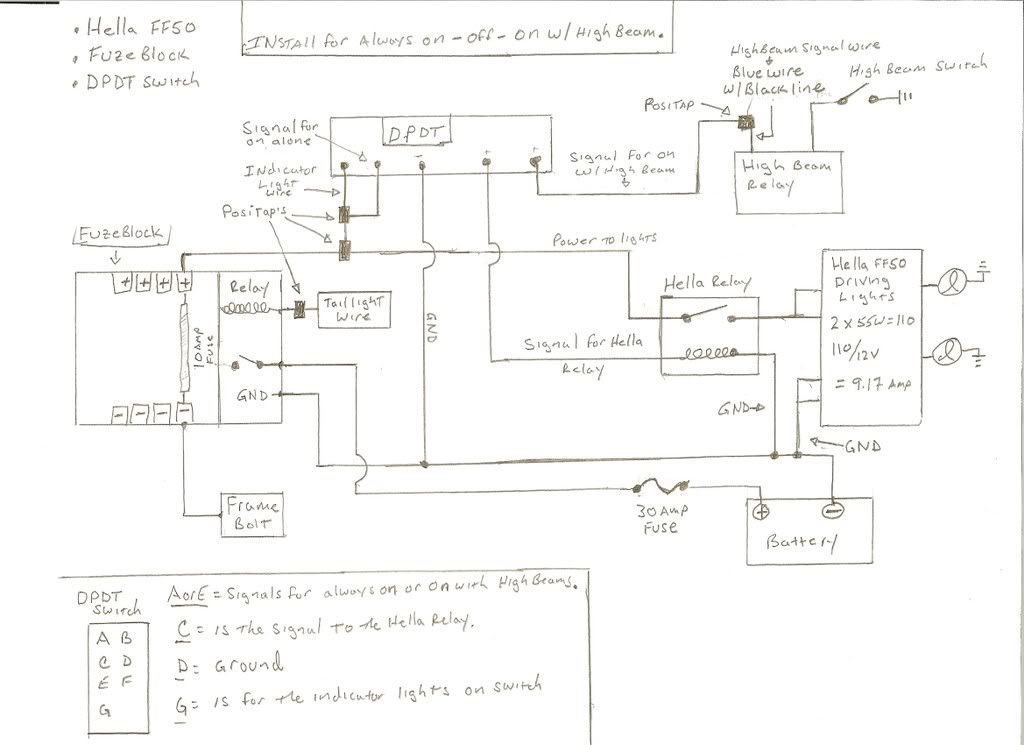
On the wiring diagram below, on the right side, there is a box labeled "hella ff50 driving lights" and that's what I don't understand.

1) there are two driving lights - why one box in the diagram?

2) there are 6 lines going into the box - what do they represent?

a) what do the cursive l's in the circles to the right of the box mean? They are connecting to ground I see, but what are they?

I know these are stupid questions, but I just don't understand electrics at all.

Thanks for any help

HellaSchematic.jpg


Last edited by a moderator:
There has been some 'artistic' work done around the Hella light box which isn't anatomically correct. The box is drawn as if the Hella lights were going into a headlight bucket that contains two bulbs, like the stock lights on the FJR. In your case, the lights should have been shown in two separate boxes. None the less, the drawing is correct, just confusing.

As drawn, the two wires in the upper left corner of the Hella box represent the two twelve volt power wires going to the two Hella lamps, one wire for each of the lamps. The bottom left corner are the two grounding wires one wire for each of the two Hella lamps.

The 'cursive I' on the right is a schematic symbol for a filament bulb. Each bulb will get one of the two power wires shown in the upper left corner. Each of the bulbs will bet one of the ground two wires shown in the lower left. Either the bulbs did not have to be shown, or the box did not need to be shown. I would have left the box out and just shown the upper power wires, one wire going to each bulb and shown one ground wire going to each bulb.

:blink: :dribble: :blink: :dribble: :blink:

If someone hasn't come along and clarified my clarification by tonight I will redraw that part of the schematic so that it is exactly correct for your install.

 
Perhaps this will help...

p590545509-4.jpg


I know, it's written in electroniceeze, but it does what you are wanting.


Latest posts

Top