Another Starter Issue

Yamaha FJR Motorcycle Forum

Help Support Yamaha FJR Motorcycle Forum:

This site may earn a commission from merchant affiliate links, including eBay, Amazon, and others.

0-8er

Member
Joined
May 23, 2010
Messages
10
Reaction score
1
Location
Bakersfield, CA
Several months ago I noticed the starter on my bike would slow down prior to the engine catching and starting. I had bought a cheap battery a year and a half before and I thought the battery was at end of life, so, time for a new one. I bought a Lithium battery to try out and the bike wouldn't even start until the third or fourth attempt, the starter would just quit spinning with the bike hot or cold. I thought the Lithium battery was bad so I returned it (Amazon) and bought a Yuasa. The starter showed the same symptoms of slowing down before the engine would catch with the Yuasa but at least the bike would start every time. That is until the day it was 108 when I rode home from work. It took four tries, the last with a cracked throttle, to start the bike so I could move it into the backyard.

I searched the forum and found wfooshee's post here among others on starter problems. I checked the ground connection from the battery to the engine, then checked the starter relay and circuit to the starter, then came to the conclusion I had a starter going out. Not something I wanted to deal with as temperatures here are cooling and prime riding season is here.

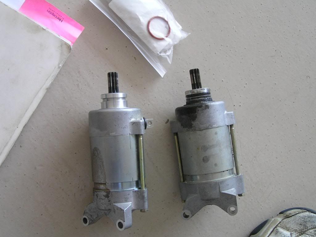
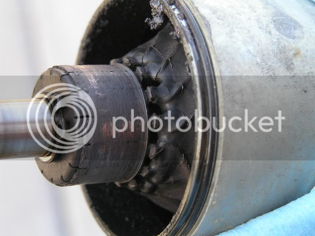
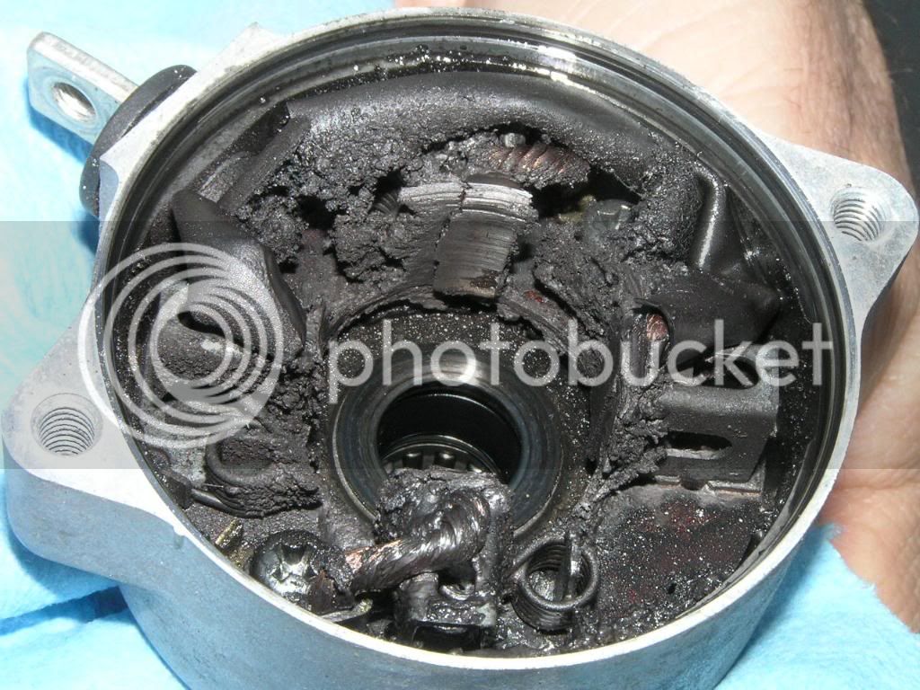
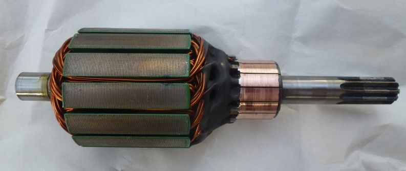
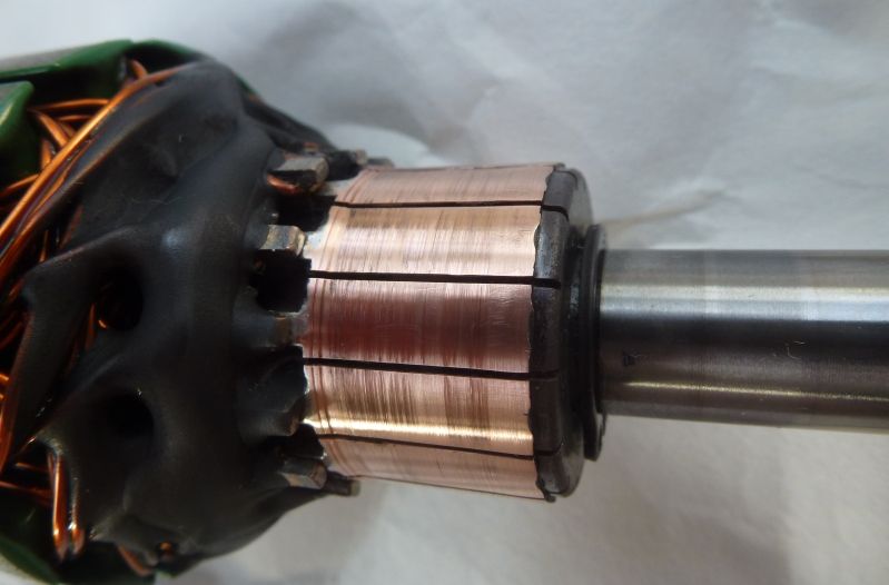
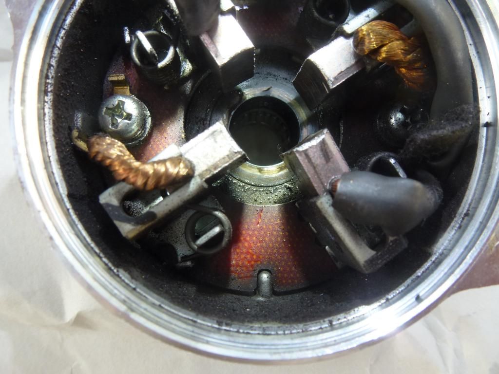
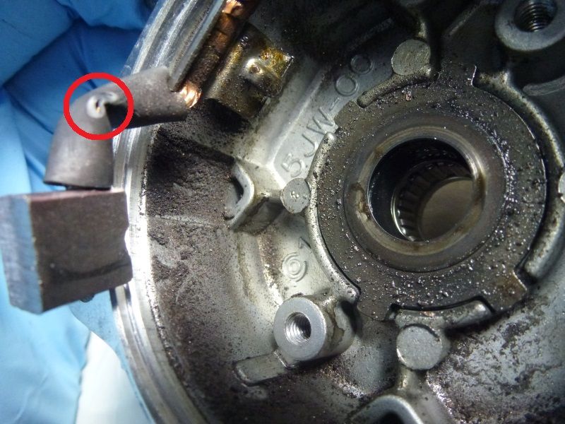
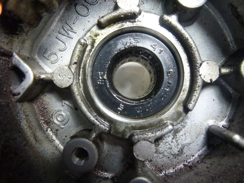
I pulled the starter out after uncovering it and ran the test wfooshee described with the starter bolted to the side rail. Even out of the engine, the starter would slow down when energized. Voltage at the starter dropped to 6.8 volts in about four seconds. Using a clamp-on ammeter, the starter current draw was 210 amps and climbing. I pulled the starter apart, it was clean inside and the brushes showed little wear just like the pictures wfooshee posted. I did notice the slots between the commutator segments were full of carbon and maybe a little oil. The commutator diameter measurement showed little if any wear.

I chucked the stator in a drill press and used 600 grit sand paper as mentioned in the manual to clean up the commutator. I cleaned the commutator slots out, measured stator resistance (OK), reassembled the starter and retested it bolted to the side rail. Voltage at the starter dropped to 11.3 volts and held steady. Based on my auditory tachometer, the starter did not slow down at all. Starter current draw was a steady 40 amps. I'm guessing carbon dust and oil shorting commutator segments together is a bad thing.

Has anyone with starter problems had success with just dressing and cleaning the commutator, then running the starter for an extended period of time?

I plan on putting the starter back in and running it. If it keeps cranking until my next valve clearance check, I may dress and clean the commutator at each valve clearance check. It only had 30,000 miles on it when I pulled it apart.

Thank you everyone who posts the problems and solutions they run into. This forum is a gold mine.

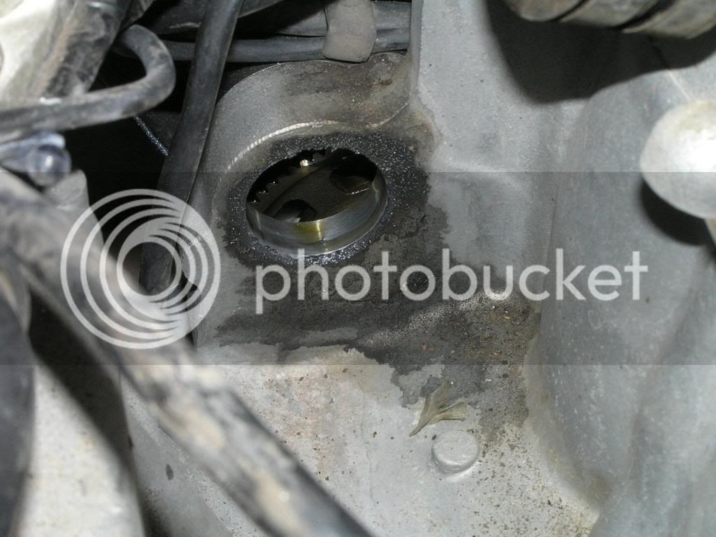
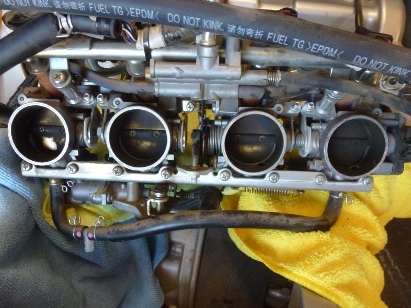
Before you say it, yes, I know I should have tested the battery first. Next time. And no, I didn't think to take pictures of the starter insides, next time also. But here's a picture of my throttle bodies. I think they need cleaning.

throttlebodies.jpg


I believe that when you have finished dressing the commutator, it is usual to undercut the mica between the segments a little.

I haven't done an FJR starter, but in all others a hacksaw blade is the correct thickness, and the undercut needs be no more than about 1/2 mm.

Yeah, that 210 Amp draw was the giveaway. If you have a clamp-on meter you could have got that reading before you swapped out a good battery for a good battery
biggrin.png


If all else is good I can think of no reason the starter should not perform well until you next have the bike apart.

 
Last edited by a moderator:
Yeah, that 210 Amp draw was the giveaway. If you have a clamp-on meter you could have got that reading before you swapped out a good battery for a good battery
biggrin.png
Twigg

I don't know much about measuring amps as I have no meter to do so. Both you and 0-8er obviously know how to do so. I was thinking to check amperage you have to disconnect the battery and run the current through the amp meter when trying to start. You spoke of a "clamp on" unit. Could you shed some light on the difference of these two methods, the accuracy of the clamp on, and by the way... how much do meters like this cost?

Just curious.

Gary

darksider #44

 
I would say that the problem with what you found was the presence of oil mixed with the brush dust. Normally the brushes wear and the dust flies off. If there is oil or grease in the area of the brushes it may have allowed the conductive brush material to cake up in the spaces between the commutator segments. Having to clean that commutator every 26k miles seems a bit excessive to me. I know of many other FJR starter motors that have lasted 100's of thousands of miles with no maintenance.

Any idea how that oil or grease might have gotten in there? Or maybe this is more of a random fluke that your got too much grease from the factory?

@Gary - Clamp on DC Ammeters

 
I see you got a link to clamp-on ammeters. They measure the current flowing through a single conductor. I guess accuracy depends a bit on quality, but even the cheapest would have picked up your problem as the normal current draw of the starter is, I think, between 70 and 90 Amps under load.

Your suggestion of "in-line" current testing is sound, but not practical for over 200 Amps. Most meters that are available or affordable measure a maximum of about 20 Amps, and usually only 10 Amps.

The build up of crud on the commutator raises the resistance between that part and the brushes, hence the larger current required to make the motor turn. Cleaning it off restores normal function, but as Fred W said, finding out why it was there will keep it working for longer.

 
QUOTE (twigg @ 03 October 2014 - 10:49 PM)

I believe that when you have finished dressing the commutator, it is usual to undercut the mica between the segments a little.
I used 600 grit sandpaper folded in half to clean the undercut. The mark left on the sandpaper showed the undercut was still deeper than the 1.5 mm minimum listed in the manual.

Yeah, that 210 Amp draw was the giveaway. If you have a clamp-on meter you could have got that reading before you swapped out a good battery for a good battery
biggrin.png
I usually do a little more troubleshooting before replacing parts but this was the second summer on the cheap battery and this summer has been hot, weeks on end over 100 and too many days at or above 105. The summer heat tends to kill batteries in my experience so I assumed it was the battery. Lesson learned. Now I have a spare.
headbonk.gif


QUOTE (Fred W @ 04 October 2014 - 5:48 am)

Any idea how that oil or grease might have gotten in there? Or maybe this is more of a random fluke that your got too much grease from the factory?
I believe the roller bearing on the gear end of the armature is lubricated by engine oil. The starter diagram in the manual shows the bearing on the gear end of the shaft has an oil seal between it and the starter internals. I think the oil seal needs to be replaced but the seal is not sold as a separate service part. I have a Kaman Industrial Technologies who carries a large variety of bearings and seals nearby, I'll see if they can match the oil seal from the armature shaft.

 
Very Interesting... I did not know about the oil seal. That would be a very logical explanation if it was weepy.

Your suggestion of "in-line" current testing is sound, but not practical for over 200 Amps. Most meters that are available or affordable measure a maximum of about 20 Amps, and usually only 10 Amps.
Technically, the way that you measure current (with the exception of a clamp-on meter) is to insert a very low high precision resistor in the series circuit and then take the voltage drop across that resistor. That is actually how an ammeter works as it has that resistance inside the meter and you place the meter in series with the circuit being tested.

The down-side, as you can imagine, are that the added resistance of the meter can have a significant influence on reading if you are reading the current of a very low resistance (low voltage, high current) circuit. Plus, in very high current situations the wattage of the series resistance is the limitation on how much current you can measure.

There are shunts available that can be placed in line to measure pretty much any amount of current. They just become cost prohibitive for higher currents.

 
Pics from SkooterG's starterectomy showing oil seal and origin of oil.....

StarterReplacement21.jpg


StarterReplacement23.jpg


.....and the results of the oil seep.....

StarterReplacement30.jpg


StarterReplacement32.jpg


Should be easy to replace with a trial fit from a seal assortment box at any competent hardware store.

 
Last edited by a moderator:
After cleaning the commutator, segment slots, and testing the starter to make sure it was good, I took it apart again to address a leaking oil seal internal to the starter.

Here is the armature. It looked good the first time I removed it except there was carbon dust mixed with oil packed into the commutator segment slots.

Armature.jpg


Close up of the commutator.

Commutator.jpg


Starter motor yoke and rear cover with bushing bearing.

magnethousingandbushingbearing.jpg


Here's the problem area, oil and carbon dust in the front cover with the brushes.

Brushesendcover01.jpg


Oil is visible on the washer and lock washer. The oil seal is the dark band just past the washers and the roller bearing can be seen at the bottom.

Brushesendcover02.jpg


After I removed the brush holder and two brushes connected to the starter front cover (negative of battery), I noticed the plastic tube on one of the brushes connected to positive lead had a hole rubbed in it. This would have blown my starter fuse if the wire in the tube touched the starter end cover.

Brushesremoved01.jpg


Here's the front cover with the washer and lock washer removed showing the oil seal.

oilseal.jpg


Picture of the seal showing the seal number for future reference.

seal.jpg


Front cover showing roller bearing and bearing number for future reference.

bearingfrominside.jpg


This shows the roller bearing from the end that goes into the engine. There is no seal on this side of the bearing which is why I think this bearing is lubricated by engine oil. The seal on the other side is supposed to keep the oil out of the starter motor which it wasn't doing very well on my starter or on SkooterG's starter shown in a previous post.

bearingfromoutside.jpg


The commutator mica undercut measured 1.87 mm, the minimum spec is 1.5 mm. The commutator diameter measured 24.74 mm, the minimum spec is 23.5 mm. Now I just need to find a seal, clean out the carbon dust/oil goo, replace the plastic tube on the positive voltage brush(es), and put it back together.

One question, has anyone replaced brushes in a starter? When I look at a Yamaha parts diagram for the starter motor, item #2 is described as a brush set. It is really a brush holder. The two negative brushes can be removed from the starter by removing a screw, one for each brush. The two positive brushes look like they are spot welded to the post for the positive battery cable which enters the starter front cover through a rubber grommet. I'd like to know if a "brush set" includes the brush holder and all four brushes.

 
Nice pictures, thank you for taking the time & trouble. This will be a useful reference source.

As for the damaged insulation blowing a fuse - you may have got some arcing & sparking but AFAIK there is no fuse in the starter system..........

 
Very Interesting... I did not know about the oil seal. That would be a very logical explanation if it was weepy.


Technically, the way that you measure current (with the exception of a clamp-on meter) is to insert a very low high precision resistor in the series circuit and then take the voltage drop across that resistor. That is actually how an ammeter works as it has that resistance inside the meter and you place the meter in series with the circuit being tested.

The down-side, as you can imagine, are that the added resistance of the meter can have a significant influence on reading if you are reading the current of a very low resistance (low voltage, high current) circuit. Plus, in very high current situations the wattage of the series resistance is the limitation on how much current you can measure.

There are shunts available that can be placed in line to measure pretty much any amount of current. They just become cost prohibitive for higher currents.
There are older auto mechanic amp meters that just sit on the wire. There is a little bracket on the back and all you do is put the wire in the bracket and turn the key.
 

Latest posts

Top