I finally tore into my ignition problem, and here's what I found.
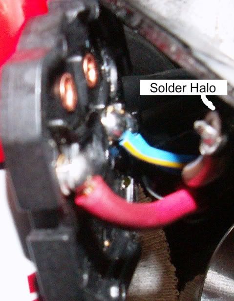
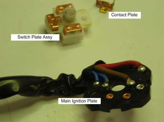
My ignition switch suffered from both problems - bad solder joint on the main ignition plate that came un-soldered, and a melted switch plate. The melted switch plate caused the contact plate in it to freeze up, and it was unable to move any longer. In this picture, you can see both failures: (note: I don't know what the official terms for these parts are so I labeled them with what I chose to call them. If anyone has heartburn over this, feel free to let me know what the correct terms are for these little critters, and I can update this post to reflect reality)
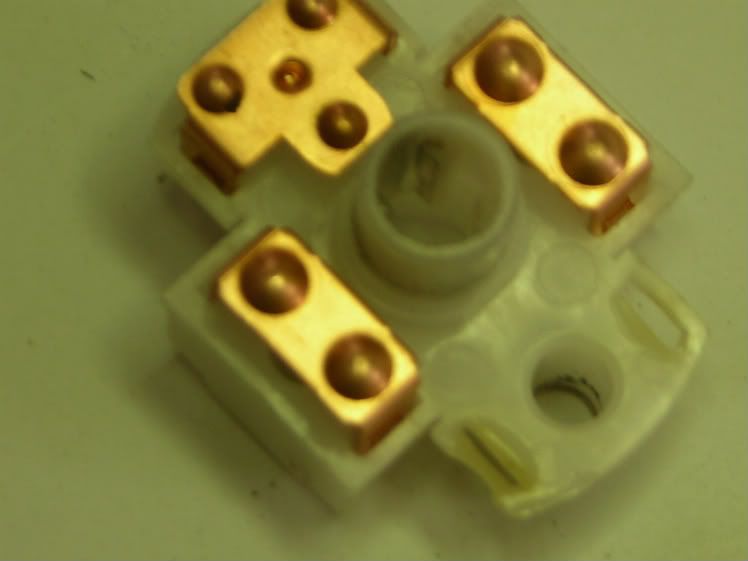
Here's a closeup of the melted switchplate (apologies for the blurry pics):
When I pulled the ignition switch apart, the main red wire was still attached by only one strand of the wire! This has to be the most likely cause of the melting of the plastic switch plate. The heat from all that current going through that one strand of wire had to cause the the plastic to melt.
I decided to try to repair the problem myself. Rather than buy a new ignition switch and simply install a newer version of the problem I already had, I decided to install a relay, similar to the solution that Brodie came up with
look here . (BTW Brodie, if we ever meet, I owe you the adult beverage of your choice!)
Resoldering the wires to the switch plate was fairly easy and straight forward. Fixing the melted plastic switch plate took a little more work. The contact plate has tabs that need to be flattened to allow it to be removed (and you will need to push them back out before you reinstall it). Once the contact plate was removed from the switch plate, I used an exacto knife (under a magnifying light) to cut open the melted slot, back to something resembling normal, so that the contact plate could move again.
If you intend to do this same repair,
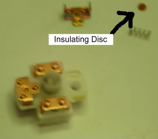
the following info is very important! The contact plate sits on top of a spring, which sits on top of a detent ball. The detent ball is what gives you the "clicks" when you turn the key. Between the detent ball and the spring there is a VERY SMALL insulating disk.
This disk is the only thing between the hot contact plate and ground! If you loose this disk or don't get it back in when you reassemble the switch plate, you will run the positive wire straight to ground! Sorry for the terrible photo, but this is the only picture that I got of the disk:
So I fixed the switch plate, and resoldered the leads to the ignition switch.
Next I spliced a relay into the system. I used almost the exact same wiring diagram that 1911 suggested
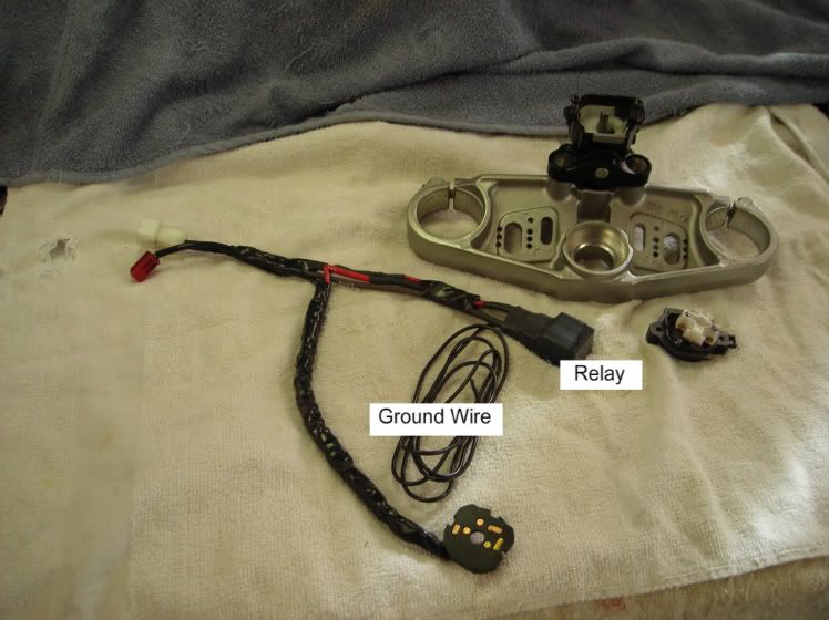
look here (and 1911, if we ever meet, I owe you the adult beverage of your choice also!) Here is a picture of the relay spliced into the harness:
The relay ground wire is the only "new" wire in this setup. You will need to find a suitable ground location for this wire.
I installed the whole shootin' match back in and attached the relay under the front of the tank, similar to what Brodie suggested. Buttoned everything up and started the bike bike up. Success! FYI, I did do continuity checks at every step. I wanted to keep trouble shooting to a minimum.
One last observation for those who intend to replace the whole ignition switch. If you don't care about the security bolts on the bottom plate of the ignition switch, then there should be no reason to deal with two keys. If you are willing to drill out the security bolts on the bottom of your existing ignition switch, as well as your replacement switch, you can simply replace the bad switch plate and main ignition plate with the two plates from the new/good ignition. Both of these items are very easy to take out and replace once you have the bottom plate off. (note that there are two sets of security bolts in the ignition switch: on holds the entire ignition switch to the upper tripple clamp, and a smaller set of bolts attaches the bottom plate. This smaller set are the ones I'm refering to).
(edited to spell "Brodie" correctly. I wanted to give proper credit for the "Brodie Relay Fix"...no disrespect meant to the forum member who goes by Brody.)


")