


One of my Iron Butt Rally 2007 checklists was to remount my Pelican case on a plate I had made.

I was pretty tickled with myself for the mounting plate, finding the recessed fasteners, and even powdercoated the plate for the original Pelican case farkle.

However, I spotted a problem. My rear subframe was cracked! So much for my fabrication skills.

So, I've been glumly thinking about the rear sub frame, priced a new one out as around $500, had a little trouble finding a welder, and generally bummed. The moment arm of the case caused too much flex for the cast aluminum to take and I had only put about 2000 miles on the rack.
I ran across Tobie Stevens that now has the FJR that is actually the 2003 bike pictured in the original article and told him about my dilemma. I made a bet that he had the same problem even though he has over 100,000 miles on the bike and pushed on the frame a bit and it seemed intact. He had an extra clamp installed and may have helped.
I also worried about Lisa's '06 as it has a Pelican installed too. We couldn't see them at the scene because they had fuel cells install, but Tobie e-mailed confirmation a couple of days later 2003 had some cracks, but happily Lisa's '06 seemed intact.
Tobie's cracks were pretty similar to mine.


But the extra clamp he had run down ran through the two round holes to reduce moment-arm flex had actually broken a chunk completely off the bike and another hairline crack.

Tobie calle a few days later and said not only did he find a welder to repair things and he had him weld in some reinforcements.
I'd have used the same welder, but he's increasingly booked up over the Spring and couldn't leave my bike for two days when I live 100 miles from home. So, I took my bike to a local guy and he was all gung-ho about fixing it and even gusseting it, but when I asked where I should park my bike he gave me a very blank look.
"……Park? I guess you could do that. You brought all your tools?"
"Yeah, the plastic pops off relatively easily and figure a wet towel under the tail will keep slag from burning things."
…another blank look. "You're not thinking of leaving the subframe on the bike are you? The high-frequency from the TIG welding could kill your electronics."
…now I have a blank look. "But, my buddy Tobie did it."
Suffice it to say that I rode the bike home and am rethinking my plan. With various ABS sensors and being in the IBR I just don't want to risk it. It's going to be a bunch of extra work, but there will be another article and pictures about about taking off my subframe.
I'm planning on starting this weekend after a RTE Saturday.
Meanwhile, I'll rethink my bracket design and have some pretty good ideas using the existing rack as a mounting point. It holds on at 5 points instead of 3. New and improved design to follow.
Part 2
Talking with a TIG welding expert on the huge amount of electromagnetic interference generated while welding I became convinced it was a more prudent choice to remove the subframe before welding. This was new ground for me on the bike and there wasn't the handy-dandy write-up like so many other parts on FJRTech.com. In fact, I'll probably submit this for inclusion.
I guestimated it to take 3 or 4 hours and would require removing the airbox, ABS unit, and who knows what. In hindsight it probably took 2 hours of work including the photo documentation. Hopefully reassembly will go more quickly.
Remove seats, sidebags, and rear rack.

Remove front plastic including black pieces under tank and side gray panels.
Remove rear plastic (two bolts and six plastic screwserts underneath). Picture shows plastic slid backwards about 4 inches.

A view of the cracked subframe and the single 6mm hex bolt that holds on the tail light assembly. It's a 5mm hex. Undo the plug, two zip ties holding the wiring harness, and snake the connector from the left side of the frame.

Taillights removed. Notice rubber grommets left and right. This is where the pins from the tail light assembly sit. Also viewable is the electrical connector to the cluster on the left side. Also, my first view of the crack from the back side.

Now the serious work starts. Unscrewing and unbolting bolts I've never done before. What I wondered is how much of the parts inside the subframe would have to be removed? Did the airbox have to be removed, the ABS unit, the tool tray, the computer, the seat release cable, etc.?
In hindsight I would have done things roughly in this order:
Remove the rear tank bracket from the frame. 4 bolts into the frame. I don't believe you need to disconnect the two over the air box. The tank doesn't move a significant amount with these bolts removed. There's also a single retainer with little tangs on the starboard side of the bike and it's easy to lose. If you lose it...and find it...don't think you've lost a second one.")

Remove the two 6mm hex on each side holding the exhaust bracket to the subframe. In my case I have a Wilbers preload adjuster in between. I just let it hang.

I removed the tool tray with two bolts into the subframe and then three Phillips screws that attach the tray to airbox. I think you need to remove the tool tray and attached computer because you'll not want to leave it attached to the subframe for welding. Also I removed the two nuts holding on the seat lock bracket in the left of the screen.

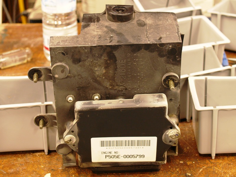
Picture of the removed tool tray and computer showing the three screws holding it to the airbox.
The underside of the wheel well plastic (the large chunk of plastic that runs from above the rear tire to points inside the guts of the bike) is held on by 2 bolts in the rear and 4 to 6 screwserts on the bottom tube of the subframe.
Also held on by screwserts is the outer cover of the airbox. It might be possible to leave it on and remove just some of the screserts, but I removed it entirely.

I also removed the crosspiece that houses the shock absorber hardness settings. Again, I have a Wilbers so I don't have the adjuster, but suffice will need to unbolt the bracket. It's held on by 4 hex heads….3 mm I think. If you have ABS…it's worthy to note that the ABS unit is attached to this bracket.

Final piece to remove is the rear brake fluid reservoir. It's held in with a single Phillips screw and then let it hang freely by the ABS unit.
You're now read to actually remove the subframe. It's only held on by six fasteners. Two 8mm hex heads (one on each side) with a nut on the backside as I show here with an allen wrench and end wrench. I don't believe these were loctited:

And the four 6mm hex heads (two each side) on the upper part of the subframe near the tank. They were Loctited with green and came loose with a loud "Pop" and flex of the allen wrench. These willl be critical to retorque when reassembling.
At this point the subframe should be free and will probably pull itself away from the bike a bit. Try moving it backwards a few inches and see if you've missed anything. Again, I believe you shouldn't have to remove the airbox (except for maybe the cover), you shouldn't have to remove the ABS unit. I purposely left on the reinforced plastic for the sidebags. Nothing electronic in there to worry about frying with TIG welding.

Here's a funny sight. Rear subframe dettached and hugger plastic resting on the tire.

An angle of the subframe free of the bike. The blue wire is a special ground I run for my aux. fuel cell.

A close-up of one of the cracks.

And a shot of the subframe I'm taking to the welder. I put back on the taillights so they'd know about critical tolerances when they repair and strenghten the frame.

Finally a couple bonus shots of things one doesn't usually see because this area of the bike isn't torn apart often.
Shot of seat release cable:

ABS unit and free-hanging rear brake reservoir. In need of some wipe-down before reassembly.

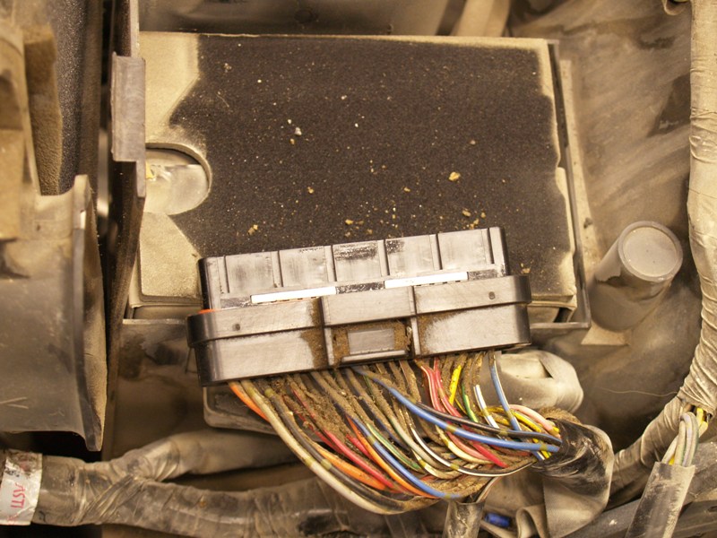
The wiring harness for the computer….after I had wiped some of the greasy crud off of it. Still needs more wiping.
Ever wonder the handhold is like? It's an add-on piece of reinforced plastic….the kind they make Rollerblades out of. It has a distinctive almost metallic "tink…tink….tink" sound when you tap it. Solid stuff. Same material for the bag slots just viewable on the right edge.

Part 3
The final installment is that I had my subframe repaired and it didn't even cost $6,000,000. It cost 80 bucks via welder Greg Brott of Kennewick and is signicantly improved!
Greg basically added a 1/4 plate on the back, cut some windows out to make sure the wires from the tail lights wouldn't rub against the metal as well as gusseting it.

A back view shows the plate and at the bottom there are additional "tabs" that roll over and span a 1/4″ gap that also adds more structural integrity.

Greg said, "I had to weld it three times. Each time I'd heat it up……the metal impurities would sweat out of it. The cast piece is not the best metal."
So, perhaps in hindsight I could have Yamaha give me a new subframe, but I wouldn't be assured it wouldn't be another subframe from the same production run. For $80 this was the best option for my piece of mind.
Next issues was the way I had my plate mounted. In the past I removed the rear rack, tied an aluminum plate straight to 3 points on subframe, and called it good. This time I took a longer, closer look at the existing rack and since it's tied into 5 different points I decided Yamaha engineers had already done a good bit of the design for me and attach my plate to the rack. It's not much to look at and has seen some hard life with bungees on my previous rear storage bag….so I drilled some holes in the beefy plastic.
Then I redrilled some holes in the alumnium plate after moving the affair as far forward as I could and still have the Pelican not interfere with the auxilliary fuel tank. It's about an inch farther forward than it was before…and a tiny bit crooked. Fasteners at bottom are the pigtail for a CB anteannae I'm adding in a near-term project.
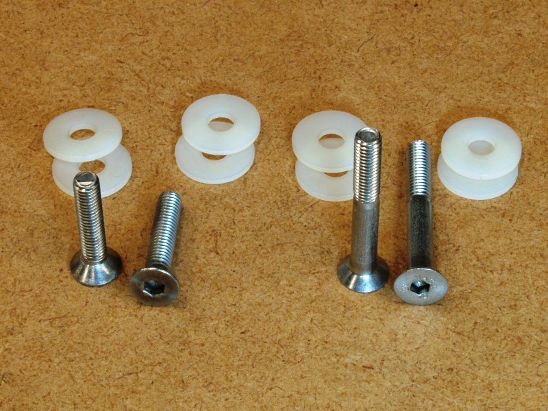
Most of my effort was driving around my hometown trying to find some very specific fasteners. 6mm x 50mm, stainless steel, recessed head screws are hard to find! While I was there I found some nylon washers that should help putting the metal through the plastic of the rack.
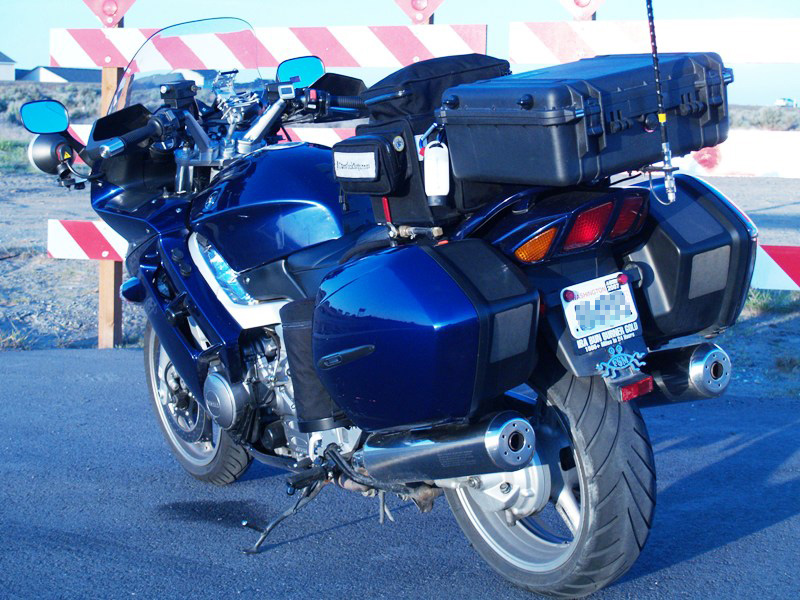
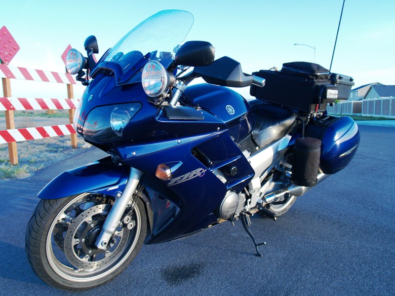
Mounted all up the bike is taking on it's heavy-weight rally shape for the 2007 season. The case will hold my camera, a set of maps, laptop, various cables, and extra storage for my GPS when not mounted on the bike. I also got a padlock and cable to secure my helmet.
ADMIN NOTE: The thread author reserves the option of merging contributory posts that help update or modify the procedure and purging off-topic posts.
I was pretty tickled with myself for the mounting plate, finding the recessed fasteners, and even powdercoated the plate for the original Pelican case farkle.
However, I spotted a problem. My rear subframe was cracked! So much for my fabrication skills.
So, I've been glumly thinking about the rear sub frame, priced a new one out as around $500, had a little trouble finding a welder, and generally bummed. The moment arm of the case caused too much flex for the cast aluminum to take and I had only put about 2000 miles on the rack.
I ran across Tobie Stevens that now has the FJR that is actually the 2003 bike pictured in the original article and told him about my dilemma. I made a bet that he had the same problem even though he has over 100,000 miles on the bike and pushed on the frame a bit and it seemed intact. He had an extra clamp installed and may have helped.
I also worried about Lisa's '06 as it has a Pelican installed too. We couldn't see them at the scene because they had fuel cells install, but Tobie e-mailed confirmation a couple of days later 2003 had some cracks, but happily Lisa's '06 seemed intact.
Tobie's cracks were pretty similar to mine.
But the extra clamp he had run down ran through the two round holes to reduce moment-arm flex had actually broken a chunk completely off the bike and another hairline crack.
Tobie calle a few days later and said not only did he find a welder to repair things and he had him weld in some reinforcements.
I'd have used the same welder, but he's increasingly booked up over the Spring and couldn't leave my bike for two days when I live 100 miles from home. So, I took my bike to a local guy and he was all gung-ho about fixing it and even gusseting it, but when I asked where I should park my bike he gave me a very blank look.
"……Park? I guess you could do that. You brought all your tools?"
"Yeah, the plastic pops off relatively easily and figure a wet towel under the tail will keep slag from burning things."
…another blank look. "You're not thinking of leaving the subframe on the bike are you? The high-frequency from the TIG welding could kill your electronics."
…now I have a blank look. "But, my buddy Tobie did it."
Suffice it to say that I rode the bike home and am rethinking my plan. With various ABS sensors and being in the IBR I just don't want to risk it. It's going to be a bunch of extra work, but there will be another article and pictures about about taking off my subframe.
I'm planning on starting this weekend after a RTE Saturday.
Meanwhile, I'll rethink my bracket design and have some pretty good ideas using the existing rack as a mounting point. It holds on at 5 points instead of 3. New and improved design to follow.
Part 2
Talking with a TIG welding expert on the huge amount of electromagnetic interference generated while welding I became convinced it was a more prudent choice to remove the subframe before welding. This was new ground for me on the bike and there wasn't the handy-dandy write-up like so many other parts on FJRTech.com. In fact, I'll probably submit this for inclusion.
I guestimated it to take 3 or 4 hours and would require removing the airbox, ABS unit, and who knows what. In hindsight it probably took 2 hours of work including the photo documentation. Hopefully reassembly will go more quickly.
Remove seats, sidebags, and rear rack.
Remove front plastic including black pieces under tank and side gray panels.
Remove rear plastic (two bolts and six plastic screwserts underneath). Picture shows plastic slid backwards about 4 inches.
A view of the cracked subframe and the single 6mm hex bolt that holds on the tail light assembly. It's a 5mm hex. Undo the plug, two zip ties holding the wiring harness, and snake the connector from the left side of the frame.
Taillights removed. Notice rubber grommets left and right. This is where the pins from the tail light assembly sit. Also viewable is the electrical connector to the cluster on the left side. Also, my first view of the crack from the back side.
Now the serious work starts. Unscrewing and unbolting bolts I've never done before. What I wondered is how much of the parts inside the subframe would have to be removed? Did the airbox have to be removed, the ABS unit, the tool tray, the computer, the seat release cable, etc.?
In hindsight I would have done things roughly in this order:
Remove the rear tank bracket from the frame. 4 bolts into the frame. I don't believe you need to disconnect the two over the air box. The tank doesn't move a significant amount with these bolts removed. There's also a single retainer with little tangs on the starboard side of the bike and it's easy to lose. If you lose it...and find it...don't think you've lost a second one.
Remove the two 6mm hex on each side holding the exhaust bracket to the subframe. In my case I have a Wilbers preload adjuster in between. I just let it hang.
I removed the tool tray with two bolts into the subframe and then three Phillips screws that attach the tray to airbox. I think you need to remove the tool tray and attached computer because you'll not want to leave it attached to the subframe for welding. Also I removed the two nuts holding on the seat lock bracket in the left of the screen.
Picture of the removed tool tray and computer showing the three screws holding it to the airbox.
The underside of the wheel well plastic (the large chunk of plastic that runs from above the rear tire to points inside the guts of the bike) is held on by 2 bolts in the rear and 4 to 6 screwserts on the bottom tube of the subframe.
Also held on by screwserts is the outer cover of the airbox. It might be possible to leave it on and remove just some of the screserts, but I removed it entirely.
I also removed the crosspiece that houses the shock absorber hardness settings. Again, I have a Wilbers so I don't have the adjuster, but suffice will need to unbolt the bracket. It's held on by 4 hex heads….3 mm I think. If you have ABS…it's worthy to note that the ABS unit is attached to this bracket.
Final piece to remove is the rear brake fluid reservoir. It's held in with a single Phillips screw and then let it hang freely by the ABS unit.
You're now read to actually remove the subframe. It's only held on by six fasteners. Two 8mm hex heads (one on each side) with a nut on the backside as I show here with an allen wrench and end wrench. I don't believe these were loctited:
And the four 6mm hex heads (two each side) on the upper part of the subframe near the tank. They were Loctited with green and came loose with a loud "Pop" and flex of the allen wrench. These willl be critical to retorque when reassembling.
At this point the subframe should be free and will probably pull itself away from the bike a bit. Try moving it backwards a few inches and see if you've missed anything. Again, I believe you shouldn't have to remove the airbox (except for maybe the cover), you shouldn't have to remove the ABS unit. I purposely left on the reinforced plastic for the sidebags. Nothing electronic in there to worry about frying with TIG welding.
Here's a funny sight. Rear subframe dettached and hugger plastic resting on the tire.
An angle of the subframe free of the bike. The blue wire is a special ground I run for my aux. fuel cell.
A close-up of one of the cracks.
And a shot of the subframe I'm taking to the welder. I put back on the taillights so they'd know about critical tolerances when they repair and strenghten the frame.
Finally a couple bonus shots of things one doesn't usually see because this area of the bike isn't torn apart often.
Shot of seat release cable:
ABS unit and free-hanging rear brake reservoir. In need of some wipe-down before reassembly.
The wiring harness for the computer….after I had wiped some of the greasy crud off of it. Still needs more wiping.
Ever wonder the handhold is like? It's an add-on piece of reinforced plastic….the kind they make Rollerblades out of. It has a distinctive almost metallic "tink…tink….tink" sound when you tap it. Solid stuff. Same material for the bag slots just viewable on the right edge.
Part 3
The final installment is that I had my subframe repaired and it didn't even cost $6,000,000. It cost 80 bucks via welder Greg Brott of Kennewick and is signicantly improved!
Greg basically added a 1/4 plate on the back, cut some windows out to make sure the wires from the tail lights wouldn't rub against the metal as well as gusseting it.
A back view shows the plate and at the bottom there are additional "tabs" that roll over and span a 1/4″ gap that also adds more structural integrity.
Greg said, "I had to weld it three times. Each time I'd heat it up……the metal impurities would sweat out of it. The cast piece is not the best metal."
So, perhaps in hindsight I could have Yamaha give me a new subframe, but I wouldn't be assured it wouldn't be another subframe from the same production run. For $80 this was the best option for my piece of mind.
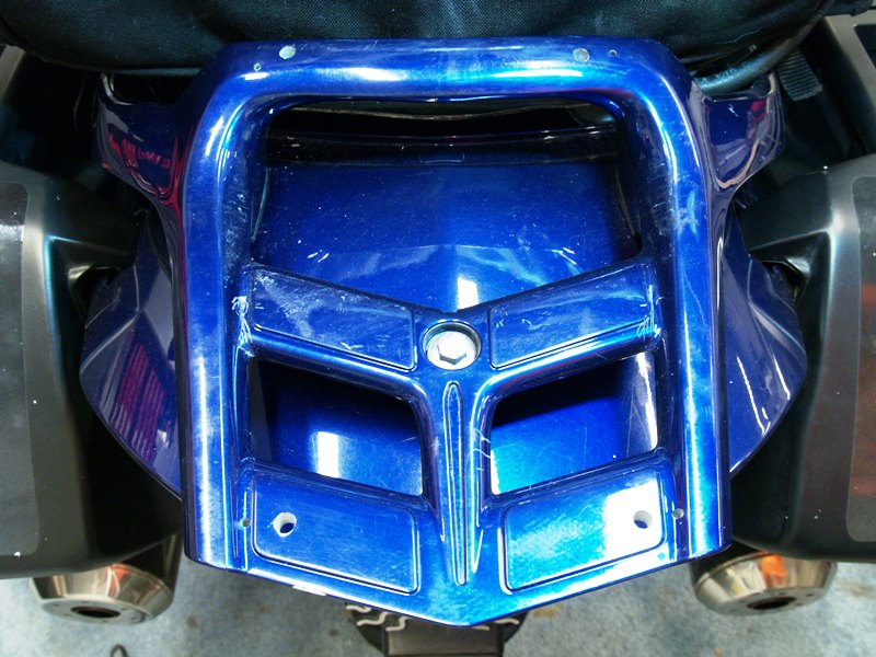
Next issues was the way I had my plate mounted. In the past I removed the rear rack, tied an aluminum plate straight to 3 points on subframe, and called it good. This time I took a longer, closer look at the existing rack and since it's tied into 5 different points I decided Yamaha engineers had already done a good bit of the design for me and attach my plate to the rack. It's not much to look at and has seen some hard life with bungees on my previous rear storage bag….so I drilled some holes in the beefy plastic.
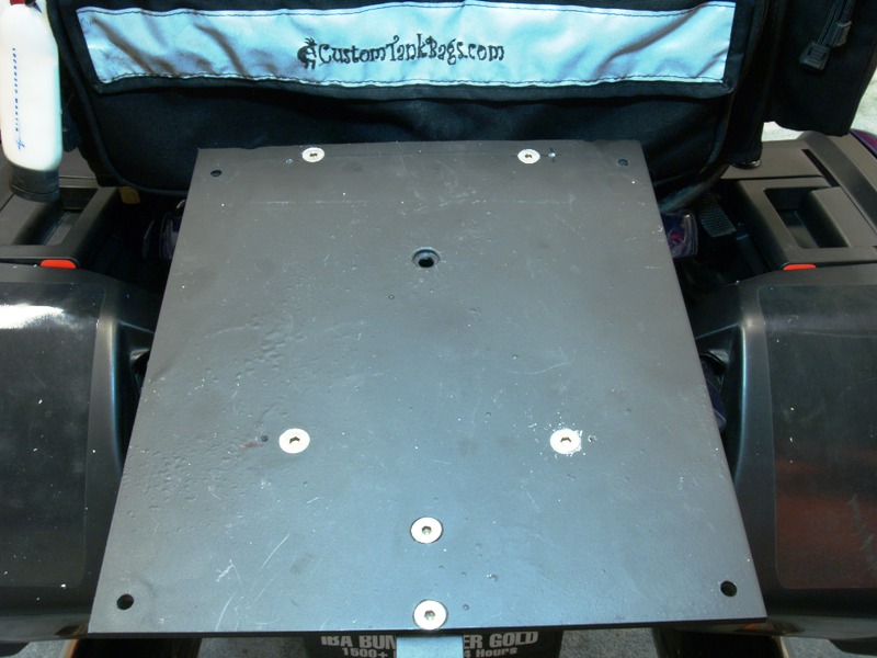
Then I redrilled some holes in the alumnium plate after moving the affair as far forward as I could and still have the Pelican not interfere with the auxilliary fuel tank. It's about an inch farther forward than it was before…and a tiny bit crooked. Fasteners at bottom are the pigtail for a CB anteannae I'm adding in a near-term project.
Most of my effort was driving around my hometown trying to find some very specific fasteners. 6mm x 50mm, stainless steel, recessed head screws are hard to find! While I was there I found some nylon washers that should help putting the metal through the plastic of the rack.
Mounted all up the bike is taking on it's heavy-weight rally shape for the 2007 season. The case will hold my camera, a set of maps, laptop, various cables, and extra storage for my GPS when not mounted on the bike. I also got a padlock and cable to secure my helmet.
ADMIN NOTE: The thread author reserves the option of merging contributory posts that help update or modify the procedure and purging off-topic posts.
Last edited by a moderator: