


torch
Well-known member
The V-56 case comes prepped for LED lighting on each side. The Givi option is real slick, with spring-loaded mating contacts that does not impact installation and removal of the trunk -- but, it's brake lights only, with only two conductors passed through the case.
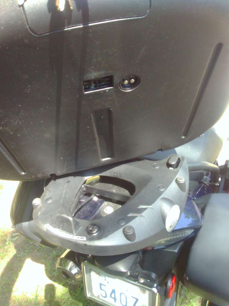
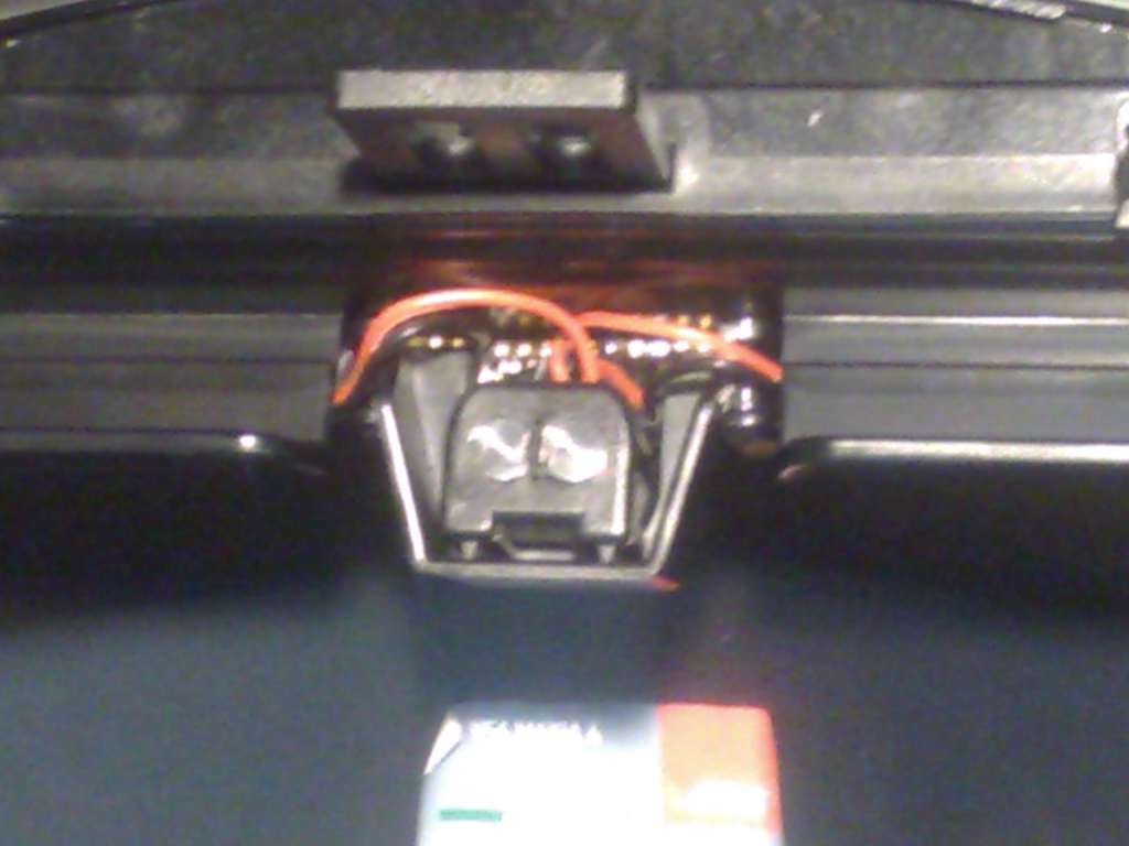
Wires run inside a provided channel up to a second set of contacts to deliver the power to the lid:
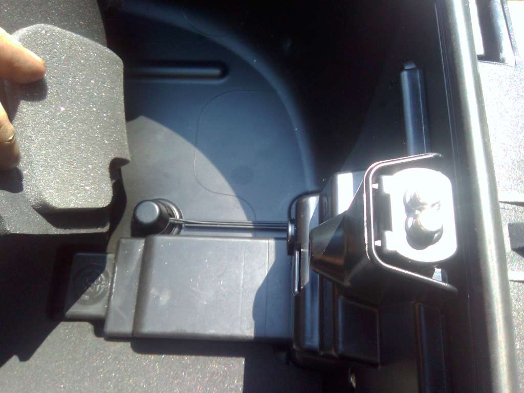
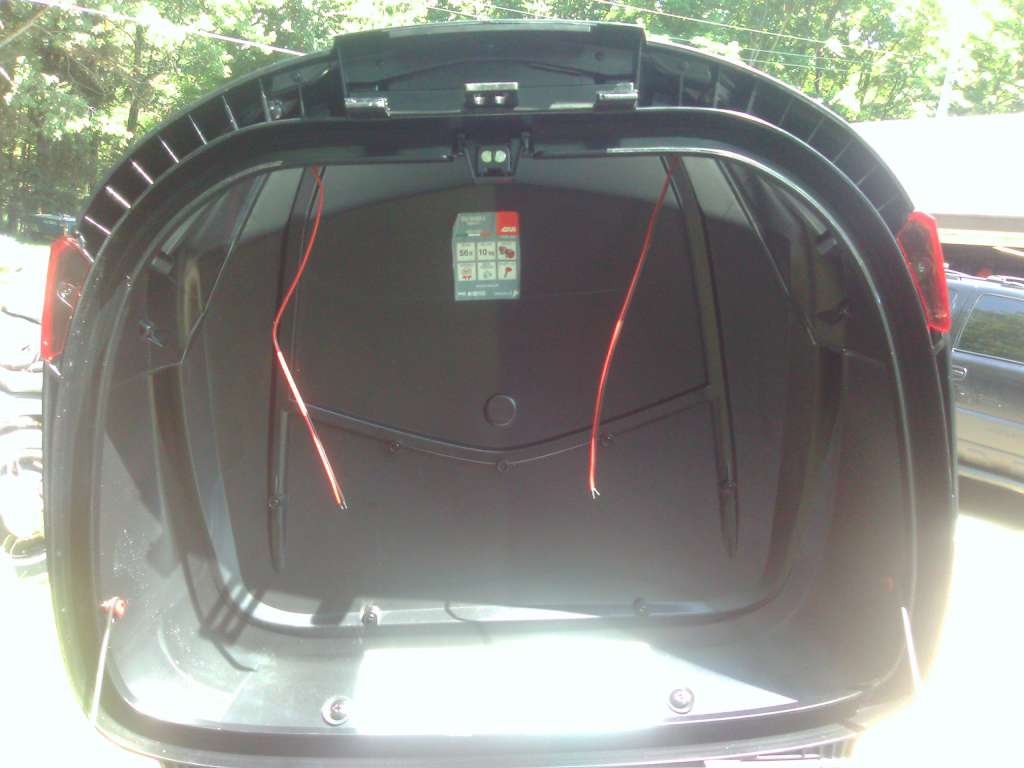
The LED strips get wired to the contacts at the centre rear of the lid:
Admore lighting offers a tail-turn-brake kit, but one must remember to hook up the twist-lock connector manually each time. And of course unhook it when removing the case. And the wiring has to be routed over the hinged side and across the inside of the lid. Not particularly elegant. Wouldn't it be nice if one could enjoy Givi's simplicity but with Admore's features?
Two conductors is all that is needed to get power up to the lid. What is needed is a way to control the lights remotely, without wires. As in Bluetooth. And with the capability to modulate the power to the LED strips through PWM. But tiny, so it can be tucked out of the way.
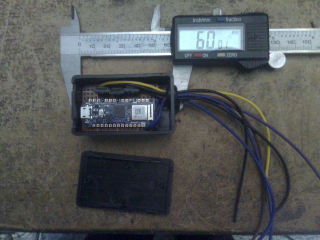
Enter the Arduino Nano 33 IOT:
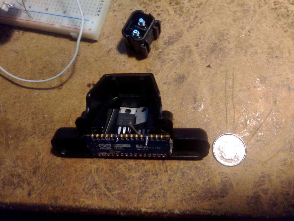
Small enough to tuck into the plastic shroud surrounding the contacts in the lid. With enough room left over for a pair of IRLB8721PB mosfets to drive the LED strips. With a pair of 330 ohm dropping resistors to bleed voltage from the gates. Note that the Nano IOT is 3.3v hardware, so the mosfet has to have a very low threshold voltage. Standard mosfets need a transistor to drive the gate at that voltage level.
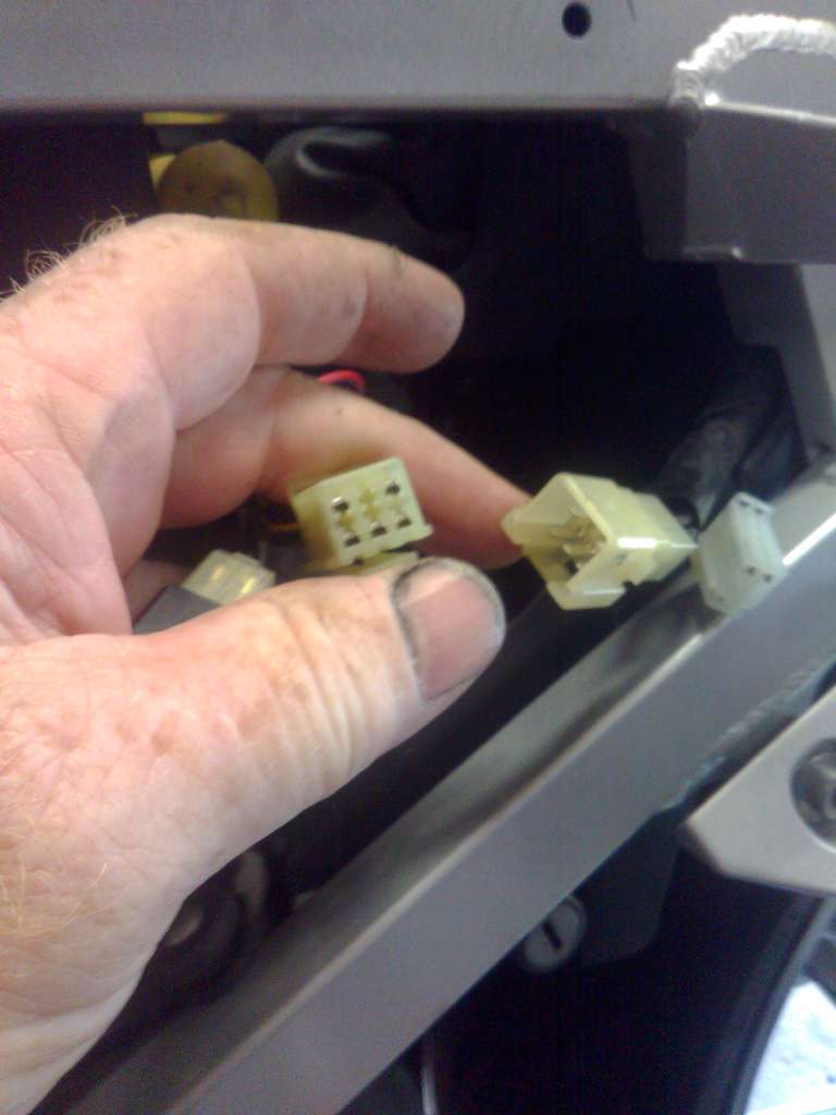
Ok, great. The lid has a receiver. No good without something to tell it what to do! First, we need access to the bike's wiring. All 5 wires are fed through a 6 position connector behind the left side panel on the GenII.
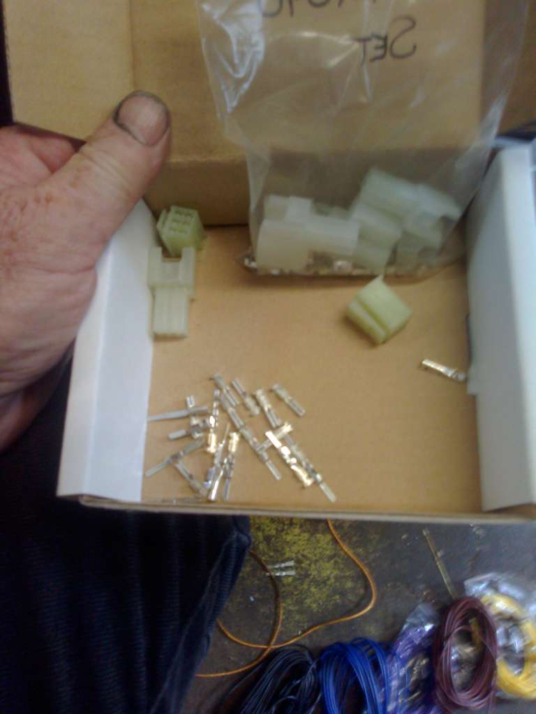
I picked up the 6 position connectors that mate with the OEM harness from Eastern Beaver. (While I was ordering, I picked up some of the 4 position connectors too -- they will mate with the ABS connector so I can replicate the unobtanium Yamaha service tool.)
I used 2 pairs to make a Y adapter. That way I can unplug the second Nano IOT without interrupting the bike's wiring, but more importantly, there are 5 fewer wires I have to squeeze into the project box. But it would work equally well to insert the Nano inline using just one pair of connectors if the box is big enough.
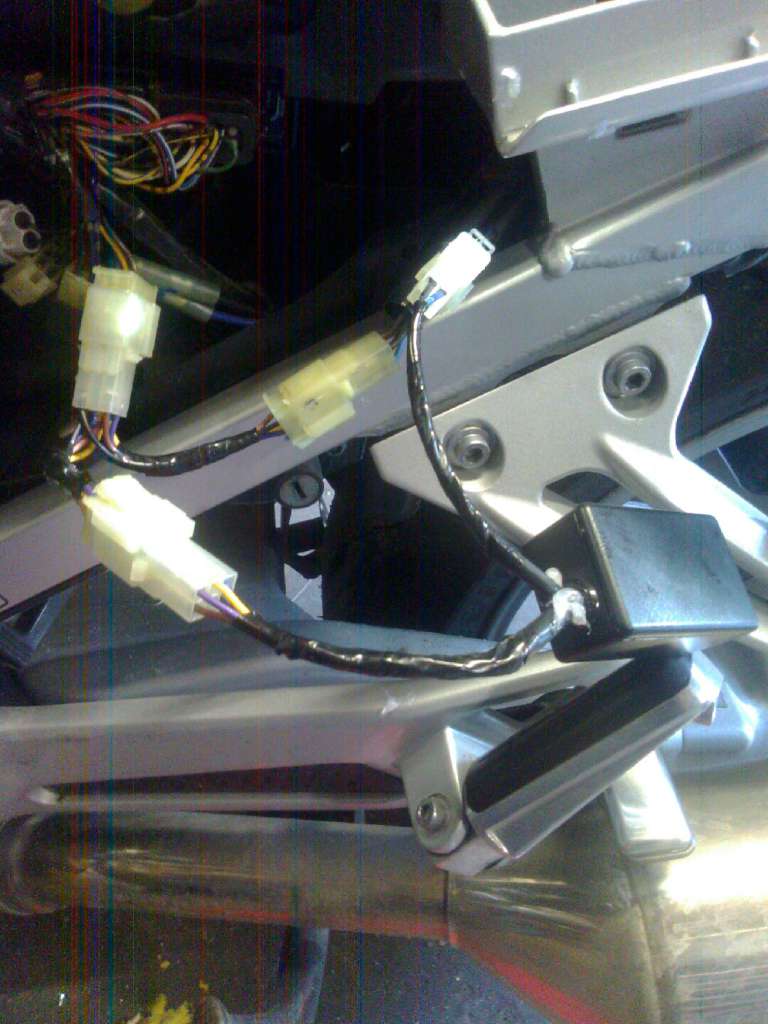
The project box contains the second Nano. I used one of the 4 position pairs for the wires to the Givi rack, because I forgot to order a 2 terminal connector pair . That box was just about the perfect size:
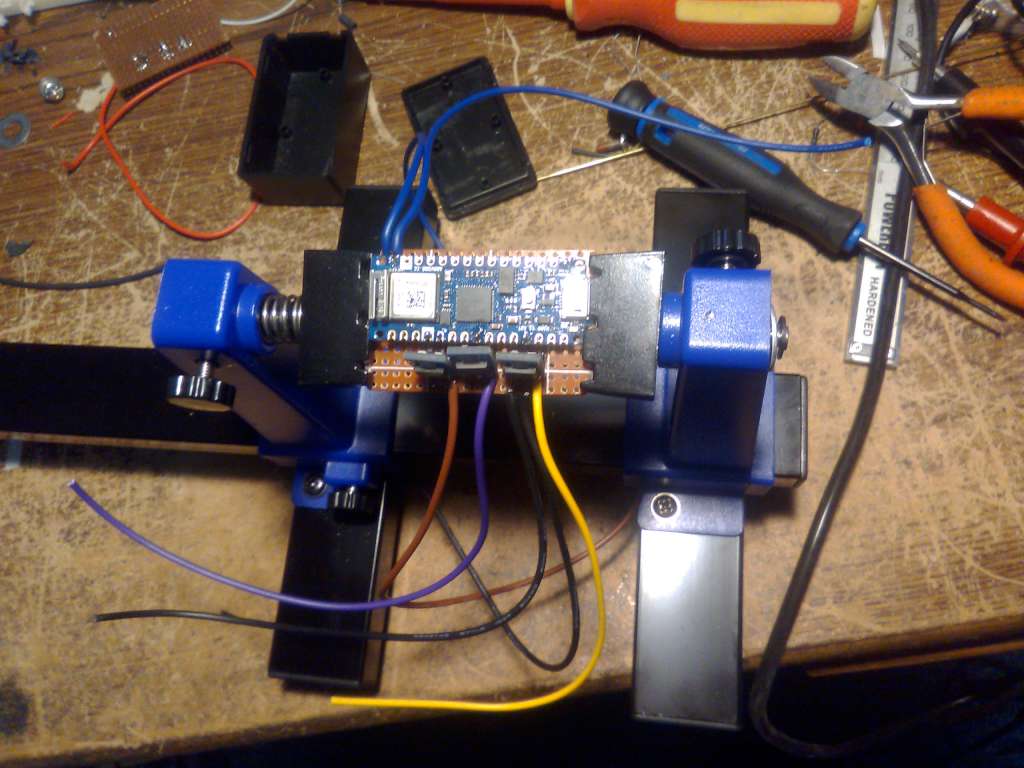
I mounted this one on a perf board, making it neater than the "dead bug" wiring needed to squeeze things into the lid. Remember, the Nano is a 3.3v device; applying the bike's 12v system direct to the input pins would cook it. I buffered the inputs with AMS1117-3.3 based buck converter modules. Very similar to a traditional TO-220 3 terminal voltage regulator (which would also work) in size and appearance, but without the live voltage heat sink tab. (Slightly different pinout too!) Each high-impedance digital input pin on the Nano requires a 10k dropping resistor to ground as well.
So the way the system works is the two units pair with each other using a unique 128 bit UUID to prevent interference from other Bluetooth devices. The pairing takes less than 2 seconds from turning on the key. The unit on the bike (called "Central" in BT Low Energy parlance) monitors the brake and turn signals. Several times a second, it sends a single digit code between 0 and 9 representing the current status to the unit in the lid (AKA the "Peripheral"), which decodes it to determine the pulse width applied to the respective LED strips. The default is 30% so if communication is lost, at least you have taillights. Brakes bump both up to 100%, etc.
Here's a short clip of the final results:
View attachment KVID2315.mp4
Wires run inside a provided channel up to a second set of contacts to deliver the power to the lid:
The LED strips get wired to the contacts at the centre rear of the lid:
Admore lighting offers a tail-turn-brake kit, but one must remember to hook up the twist-lock connector manually each time. And of course unhook it when removing the case. And the wiring has to be routed over the hinged side and across the inside of the lid. Not particularly elegant. Wouldn't it be nice if one could enjoy Givi's simplicity but with Admore's features?
Two conductors is all that is needed to get power up to the lid. What is needed is a way to control the lights remotely, without wires. As in Bluetooth. And with the capability to modulate the power to the LED strips through PWM. But tiny, so it can be tucked out of the way.
Enter the Arduino Nano 33 IOT:
Small enough to tuck into the plastic shroud surrounding the contacts in the lid. With enough room left over for a pair of IRLB8721PB mosfets to drive the LED strips. With a pair of 330 ohm dropping resistors to bleed voltage from the gates. Note that the Nano IOT is 3.3v hardware, so the mosfet has to have a very low threshold voltage. Standard mosfets need a transistor to drive the gate at that voltage level.
Ok, great. The lid has a receiver. No good without something to tell it what to do! First, we need access to the bike's wiring. All 5 wires are fed through a 6 position connector behind the left side panel on the GenII.
I picked up the 6 position connectors that mate with the OEM harness from Eastern Beaver. (While I was ordering, I picked up some of the 4 position connectors too -- they will mate with the ABS connector so I can replicate the unobtanium Yamaha service tool.)
I used 2 pairs to make a Y adapter. That way I can unplug the second Nano IOT without interrupting the bike's wiring, but more importantly, there are 5 fewer wires I have to squeeze into the project box. But it would work equally well to insert the Nano inline using just one pair of connectors if the box is big enough.
The project box contains the second Nano. I used one of the 4 position pairs for the wires to the Givi rack, because I forgot to order a 2 terminal connector pair
. That box was just about the perfect size:
I mounted this one on a perf board, making it neater than the "dead bug" wiring needed to squeeze things into the lid. Remember, the Nano is a 3.3v device; applying the bike's 12v system direct to the input pins would cook it. I buffered the inputs with AMS1117-3.3 based buck converter modules. Very similar to a traditional TO-220 3 terminal voltage regulator (which would also work) in size and appearance, but without the live voltage heat sink tab. (Slightly different pinout too!) Each high-impedance digital input pin on the Nano requires a 10k dropping resistor to ground as well.
So the way the system works is the two units pair with each other using a unique 128 bit UUID to prevent interference from other Bluetooth devices. The pairing takes less than 2 seconds from turning on the key. The unit on the bike (called "Central" in BT Low Energy parlance) monitors the brake and turn signals. Several times a second, it sends a single digit code between 0 and 9 representing the current status to the unit in the lid (AKA the "Peripheral"), which decodes it to determine the pulse width applied to the respective LED strips. The default is 30% so if communication is lost, at least you have taillights. Brakes bump both up to 100%, etc.
Here's a short clip of the final results:
View attachment KVID2315.mp4
Last edited:


