0Face
Well-known member
I installed the Hella FF50 Driving lights with a DPDT (double pole double throw) switch. This gives me the ability to have the lights on by themselves or off completely or connected to the bright lights so when I flip on the bright the FF50s come on too. I used the FuzeBlock so I can add more accessories later.
(disclaimer – I used a couple pictures from other posts because they were either better or I forgot to take a picture of it.)
Basic Part List:
Garauld Brackets (he does great work, I have the small rack he makes too)
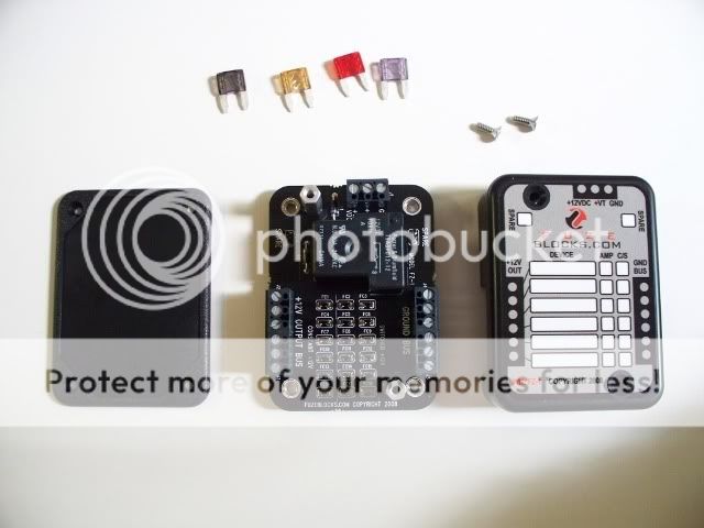
FuzeBlock
Hella FF50 Driving Lights
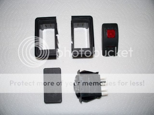
DPDT Switch and housing
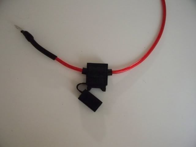
30 Amp inline fuse
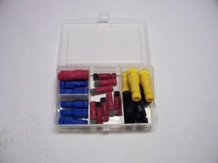
Wire & Connectors
Posi-Tap Connectors
Tracy Martin’s Motorcycle Electrical System Book
Patience & help
Here’s what the Garauld brackets look like:
This is the FuzeBlock www.FuzeBlocks.com : It’s really cool because you have one spot where you can wire either switched power (on when the bike is on) or always on power. It has its own relay built in.
DPDT Switch that I got from Electrical Connection (thanks to John Dumke’s install post)
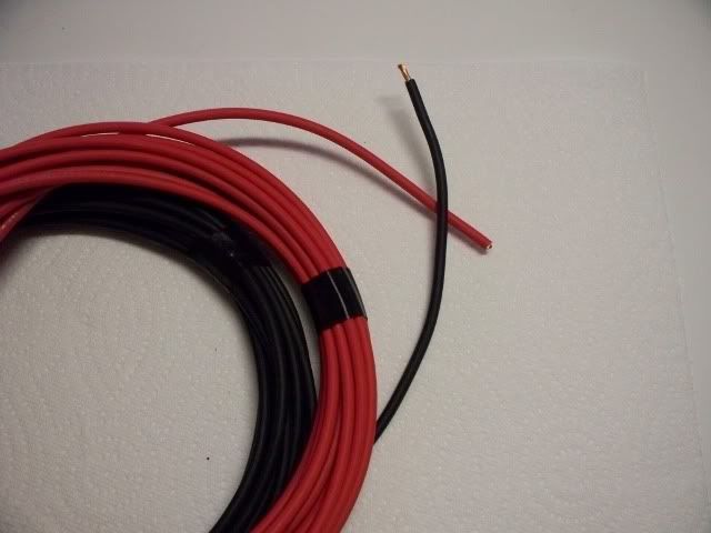
I got the wire, some basic connectors, and heat shrink tubing from Wiring Products
The wire I went with was a little overkill I think. I used 12 Gauge SXL Cross-linked Automotive Wire. It’s supposed to be more heat resistant. I could have gone with a smaller gauge (the gauges get smaller as the numbers go up – 16 is smaller than 12 – like shotguns).
Here is how I did it.
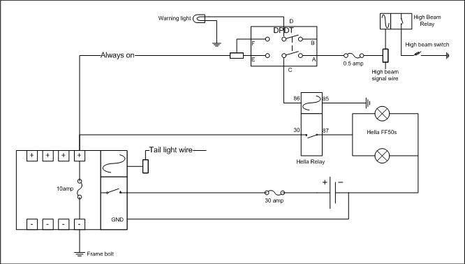
After I did it all I made this Schematic (I recommend doing the schematic FIRST!)
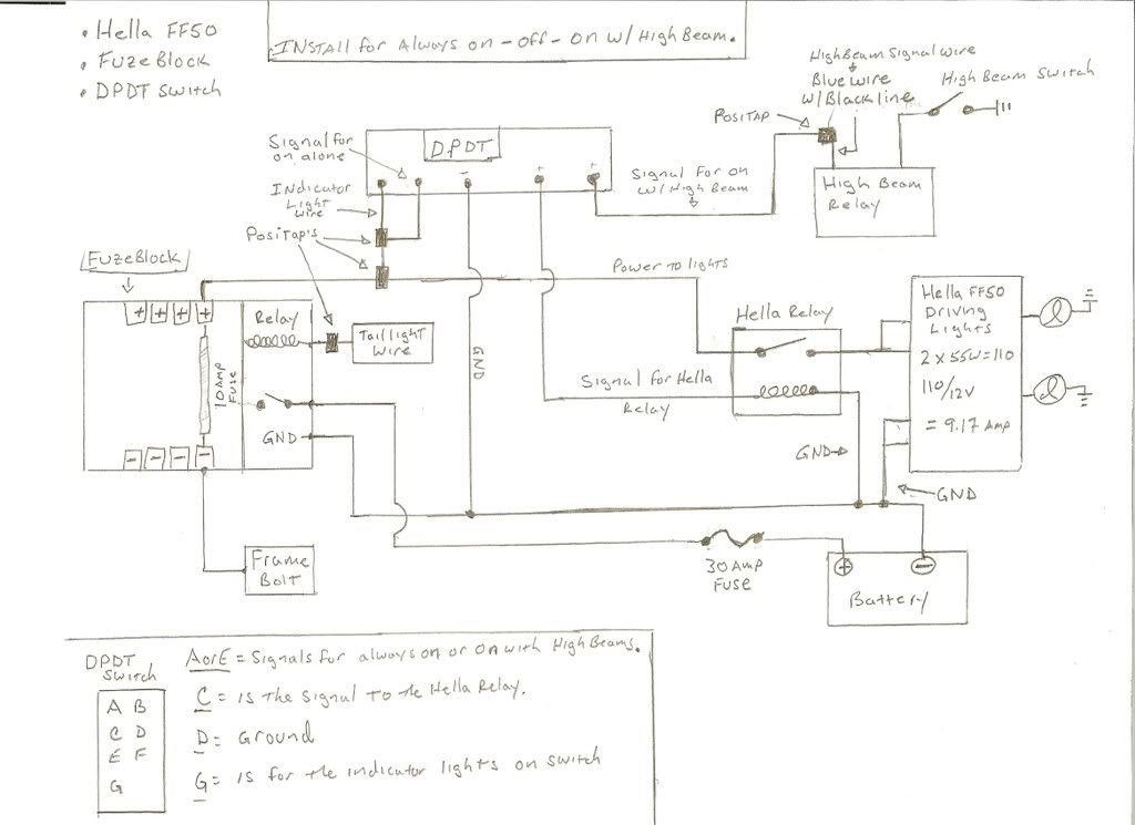
A quick explanation of the relays used here (correct me if I’m wrong). The relays are open circuits, meaning that they interrupt the flow of current. There is a small magnet inside that when current (signal) is applied to it it closes the circuit allowing the main “pass through” current to connect to the circuit. How I interpreted this is, you can run larger amperage through the relay while using a smaller signal wire to activate the relay. Kind of like a draw-bridge operator, except the bridge is always up until some cars need to cross. This way you don’t pull too much amperage from the signal wire through the switch. Sorry if this is too basic but that’s why I wanted to post this.
I put a terminal connector on the 30Amp Fuse holder and connected it to the main power wire for the FuzeBlock. I put the 30A fuse near the battery to prevent any shorts or melted wires farther down the circuit from causing a fire or my hair to stand up. Did the same for the ground wire (minus the fuse).
I ran the wires for the FuzeBlock down the right side.
I zip tied them and tucked them in.
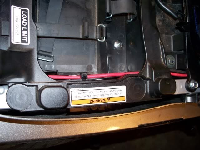
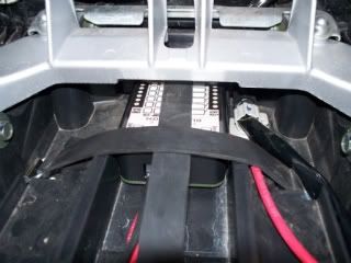
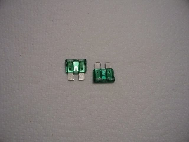
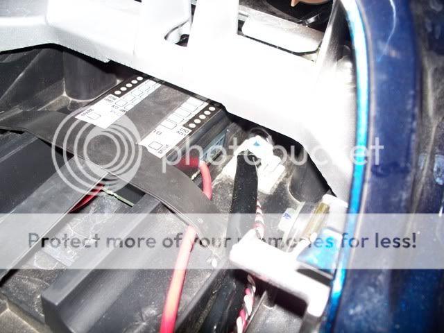
Connected them to the FuzeBlock. This Picture has the power for the lights and the ground wired too. It has the 10A fuse in place. The lights draw 9.17A.
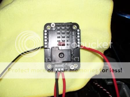
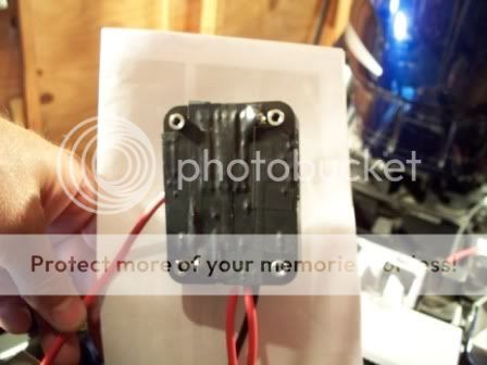
I taped the back of the block just to be sure the soldering points wouldn't be exposed.
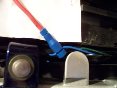
I tapped into the tail light for the signal for the relay inside the FuzeBlock. The blue wire is the running light. I used a Posi-Tap.
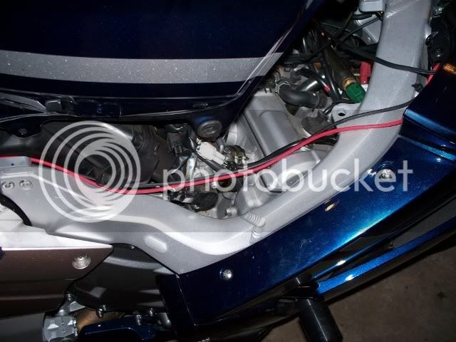
I pulled the power for the lights from the FuzeBlock up the left side of the bike grounded the circuit to a frame bolt back by the FuzeBlock.
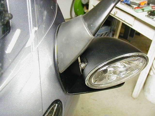
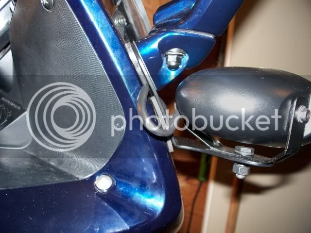
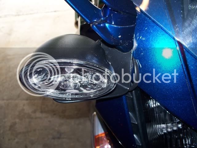
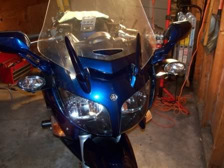
I took off the mirrors and installed the brackets and lights. You have to remove panels A, B, C, & D to get at the bolts for the mirrors and run the wires around the front. I put an extra piece of rubber I cut from an inner tube between the bracket and the mirror because I was concerned about vibration. Garauld’s brackets come with a rubber mounting to put between the bike and the bracket. I glued that to the bracket. I heat shrink wrapped the wires for the lights and ran them through the vent in the front of the cowling.
I ran the wires through the front of the cowling and ran a ground wire to the negative on the battery. There is a perfect little channel in there but it requires a stiff piece of wire to help pull the wire through. I used a section of coat hanger wire.
(forgot to get a picture of it but you'll see it)
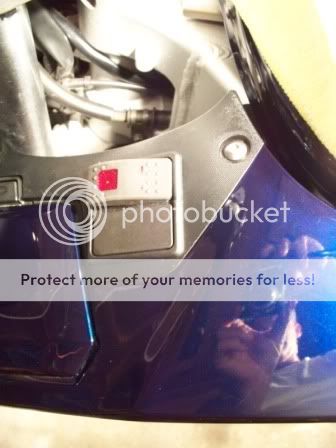
Now you’ll have all the wires over by where you put the switch. I used the grip heater spot for the switch because I don’t have grip warmers. You’ll have to open it up a little more to accommodate the bezel for the switch. Used a Dremel tool. Be careful though. It’s easy to get going with that thing.
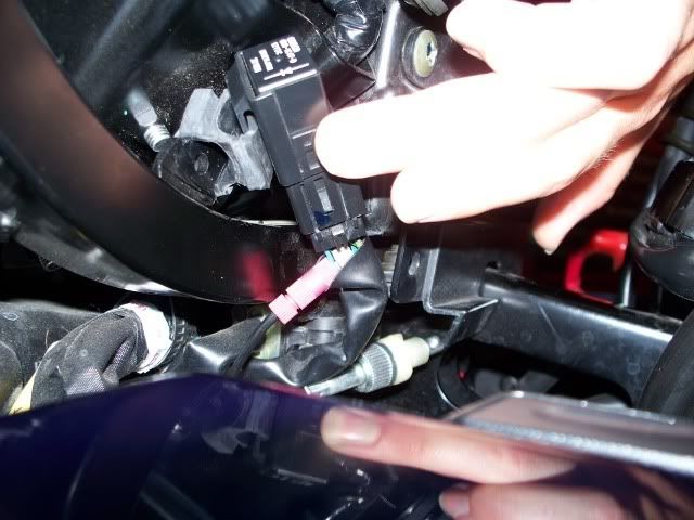
I tapped into the wire for the high beam relay for the high beam signal side of the switch. I used the blue wire with a black line on it. Here’s where those Posi-Taps come in really handy. A multi-meter for testing voltage and current is a really useful tool and you can find them pretty cheap. The easiest way to test stuff that is plugged in is to use the probe to get at the connection from the back where the wires go into the harness. Below the HB relay is the headlight adjustment cable. That thing was designed to get in the way of everything.
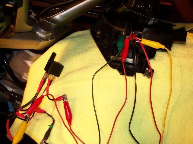
What I found incredibly useful (the second time I wired this), were those little jumper cables. No more electrical tape and trying to hold wires while testing. Here I’m testing the circuit to see if I have the connection points correct.
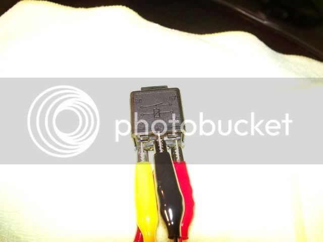
The Hella relay has a diagram on it the shows which terminals are for the circuit and which are for the signal. 30 & 87 are for the switch part of the relay (on some relays there’s an 87a also). 85 & 86 are for the signal and ground.
The DPDT switch connections are on the Schematic. Thanks again to John Dumke’s Post. I used the high beam splice for signal to the switch for on with the HB. I tapped off the power coming from the FuzeBlock to signal the “on by themselves” and another tap to power the indicator lights on the switch. So, there are two inputs to the switch, plus the indicator light input and one out from the switch the Hella relay to trigger the lights. The power for the lights comes directly from the FuzeBlock to the Hella relay not through the switch. (I had it wired through the switch originally but it was pointed out that there might be a better way). All the components: lights, switch, and Hella relay are grounded to the battery.
Try not to make the connection wires too short in your attempt to make everything neat. I did it and it blows when you run out of connectors and try to get to Radio Shack in 10 minutes, before they close and they’re 20 minutes away. :fool:
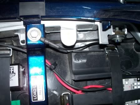
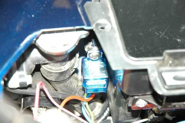
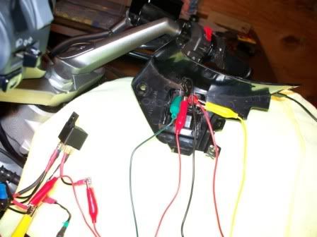
The picture I took form John’s post (his was a better shot) shows where to put the Hella relay. It is just to the rear of the glovebox. It really is like they put that bolt there just for it.
Test everything again before you put all back together.
This time, test everything, then label the wires, then put it all back together.
:angry: DON'T FORGET TO PUT THE 30A FUSE IN THE FUSE HOLDER! You might spend an hour trying to figure out why it all doesn't work... or so I've heard.
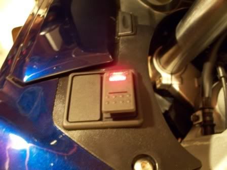
Check out the indicator lights
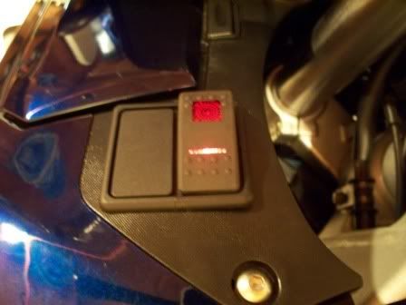
Back together:
Thanks to Aaron and Erin for their help! :clapping:
I hope this helps somebody.
Thanks for the FJR Forum.
(disclaimer – I used a couple pictures from other posts because they were either better or I forgot to take a picture of it.)
Basic Part List:
Garauld Brackets (he does great work, I have the small rack he makes too)
FuzeBlock
Hella FF50 Driving Lights
DPDT Switch and housing
30 Amp inline fuse
Wire & Connectors
Posi-Tap Connectors
Tracy Martin’s Motorcycle Electrical System Book
Patience & help
Here’s what the Garauld brackets look like:
This is the FuzeBlock www.FuzeBlocks.com : It’s really cool because you have one spot where you can wire either switched power (on when the bike is on) or always on power. It has its own relay built in.
DPDT Switch that I got from Electrical Connection (thanks to John Dumke’s install post)
I got the wire, some basic connectors, and heat shrink tubing from Wiring Products
The wire I went with was a little overkill I think. I used 12 Gauge SXL Cross-linked Automotive Wire. It’s supposed to be more heat resistant. I could have gone with a smaller gauge (the gauges get smaller as the numbers go up – 16 is smaller than 12 – like shotguns).
Here is how I did it.
After I did it all I made this Schematic (I recommend doing the schematic FIRST!)
A quick explanation of the relays used here (correct me if I’m wrong). The relays are open circuits, meaning that they interrupt the flow of current. There is a small magnet inside that when current (signal) is applied to it it closes the circuit allowing the main “pass through” current to connect to the circuit. How I interpreted this is, you can run larger amperage through the relay while using a smaller signal wire to activate the relay. Kind of like a draw-bridge operator, except the bridge is always up until some cars need to cross. This way you don’t pull too much amperage from the signal wire through the switch. Sorry if this is too basic but that’s why I wanted to post this.
I put a terminal connector on the 30Amp Fuse holder and connected it to the main power wire for the FuzeBlock. I put the 30A fuse near the battery to prevent any shorts or melted wires farther down the circuit from causing a fire or my hair to stand up. Did the same for the ground wire (minus the fuse).
I ran the wires for the FuzeBlock down the right side.
I zip tied them and tucked them in.
Connected them to the FuzeBlock. This Picture has the power for the lights and the ground wired too. It has the 10A fuse in place. The lights draw 9.17A.
I taped the back of the block just to be sure the soldering points wouldn't be exposed.
I tapped into the tail light for the signal for the relay inside the FuzeBlock. The blue wire is the running light. I used a Posi-Tap.
I pulled the power for the lights from the FuzeBlock up the left side of the bike grounded the circuit to a frame bolt back by the FuzeBlock.
I took off the mirrors and installed the brackets and lights. You have to remove panels A, B, C, & D to get at the bolts for the mirrors and run the wires around the front. I put an extra piece of rubber I cut from an inner tube between the bracket and the mirror because I was concerned about vibration. Garauld’s brackets come with a rubber mounting to put between the bike and the bracket. I glued that to the bracket. I heat shrink wrapped the wires for the lights and ran them through the vent in the front of the cowling.
I ran the wires through the front of the cowling and ran a ground wire to the negative on the battery. There is a perfect little channel in there but it requires a stiff piece of wire to help pull the wire through. I used a section of coat hanger wire.
(forgot to get a picture of it but you'll see it)
Now you’ll have all the wires over by where you put the switch. I used the grip heater spot for the switch because I don’t have grip warmers. You’ll have to open it up a little more to accommodate the bezel for the switch. Used a Dremel tool. Be careful though. It’s easy to get going with that thing.
I tapped into the wire for the high beam relay for the high beam signal side of the switch. I used the blue wire with a black line on it. Here’s where those Posi-Taps come in really handy. A multi-meter for testing voltage and current is a really useful tool and you can find them pretty cheap. The easiest way to test stuff that is plugged in is to use the probe to get at the connection from the back where the wires go into the harness. Below the HB relay is the headlight adjustment cable. That thing was designed to get in the way of everything.
What I found incredibly useful (the second time I wired this), were those little jumper cables. No more electrical tape and trying to hold wires while testing. Here I’m testing the circuit to see if I have the connection points correct.
The Hella relay has a diagram on it the shows which terminals are for the circuit and which are for the signal. 30 & 87 are for the switch part of the relay (on some relays there’s an 87a also). 85 & 86 are for the signal and ground.
The DPDT switch connections are on the Schematic. Thanks again to John Dumke’s Post. I used the high beam splice for signal to the switch for on with the HB. I tapped off the power coming from the FuzeBlock to signal the “on by themselves” and another tap to power the indicator lights on the switch. So, there are two inputs to the switch, plus the indicator light input and one out from the switch the Hella relay to trigger the lights. The power for the lights comes directly from the FuzeBlock to the Hella relay not through the switch. (I had it wired through the switch originally but it was pointed out that there might be a better way). All the components: lights, switch, and Hella relay are grounded to the battery.
Try not to make the connection wires too short in your attempt to make everything neat. I did it and it blows when you run out of connectors and try to get to Radio Shack in 10 minutes, before they close and they’re 20 minutes away. :fool:
The picture I took form John’s post (his was a better shot) shows where to put the Hella relay. It is just to the rear of the glovebox. It really is like they put that bolt there just for it.
Test everything again before you put all back together.
This time, test everything, then label the wires, then put it all back together.
:angry: DON'T FORGET TO PUT THE 30A FUSE IN THE FUSE HOLDER! You might spend an hour trying to figure out why it all doesn't work... or so I've heard.
Check out the indicator lights
Back together:
Thanks to Aaron and Erin for their help! :clapping:
I hope this helps somebody.
Thanks for the FJR Forum.
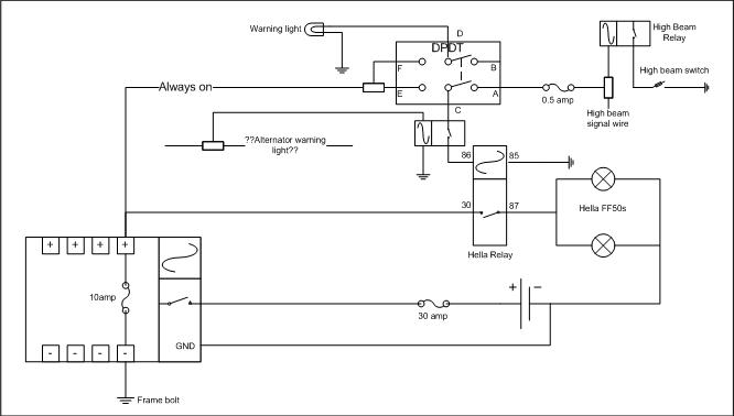
") Firstly thanks for that schematic (and write-up) 0Face. Just what I was looking for. However, I'm having a hard time finding a DPDT switch with a warning light in this neck of the woods, so an electrical engineering friend suggested I add my own. He also suggested I add a fuse between the high beam signal wire and the DPDT switch just to play safe should something go haywire on the main beam circuit.
Firstly thanks for that schematic (and write-up) 0Face. Just what I was looking for. However, I'm having a hard time finding a DPDT switch with a warning light in this neck of the woods, so an electrical engineering friend suggested I add my own. He also suggested I add a fuse between the high beam signal wire and the DPDT switch just to play safe should something go haywire on the main beam circuit.