KrZy8 Gen2 - Charging Circuit

Yamaha FJR Motorcycle Forum

Help Support Yamaha FJR Motorcycle Forum:

This site may earn a commission from merchant affiliate links, including eBay, Amazon, and others.
OK, I think I got somewhat of what you were saying ionbeam. So I pulled up a video about checking the stator and rectifier and there was one test I didn't do, because the SM didn't mention it; I hadn't checked the stator wiring to ground to see if there was any shorts. Setting the multimeter at 200ohm, all the three white wires show a value of 1 when checking to ground. The ohms checking between the three A,B,C phases are equal at .9ohm. The voltage at the white wires all go up to around 80v when revving the engine.... But is all that possible to get the right numbers but it show shorts in all three wires? Or am I just not checking things right?
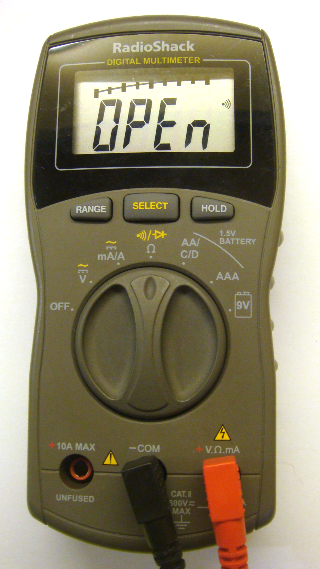
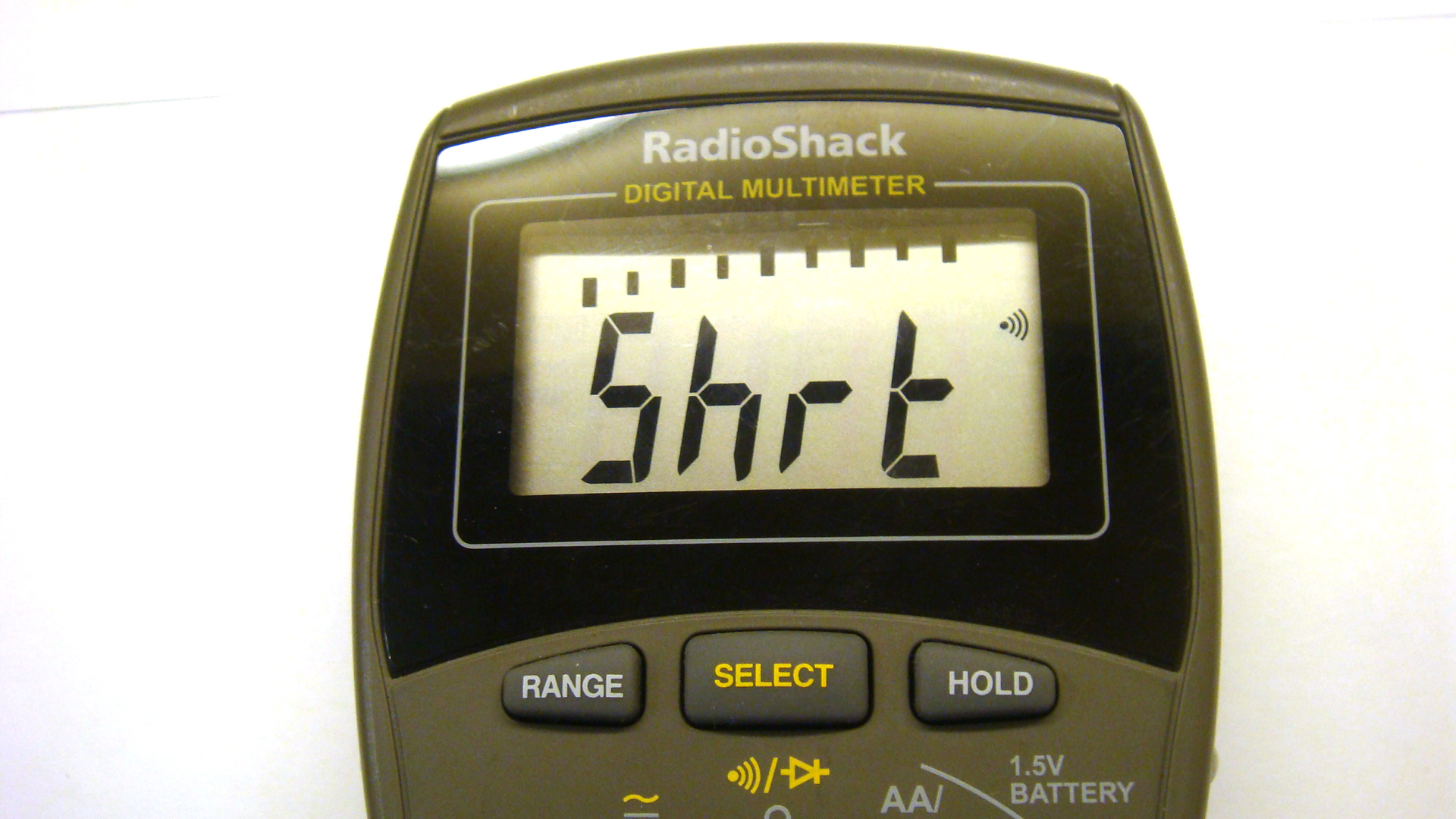
You have a problem if you do measure 1 ohm to ground on any/all of the stator wires, they should not have any connection to ground.

All three are connected together internally, so if one shows a connection to ground, all three will. It's difficult to make accurate resistance measurement at sub-one ohm values, but it is curious that all three measure the same.

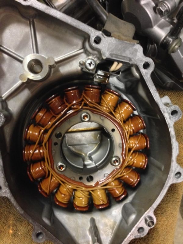
Most likely is where the wires pass through the casing, but I'd expect one of the three wires to read a lower value to ground than the other two.

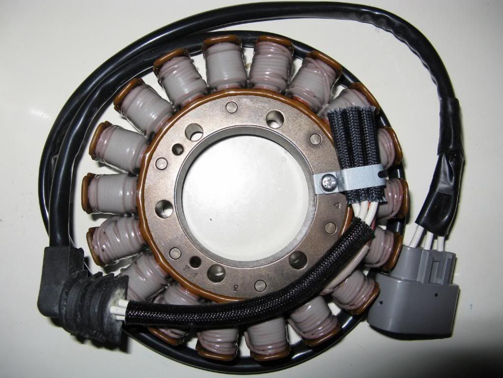
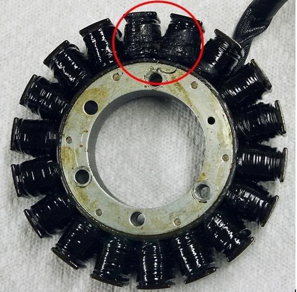
It does look as if an internal inspection is required, it's not difficult to remove the stator cover.

 
Even though the electrical system is DC there can be a lot of AC noise riding on the DC. This is the electrical system of my FJR at idle; what you see is the noise riding on top of the 14 volts on the positive post at the battery.
What are the scales? Enquiring minds want to know
smile.png
.
That was done so long ago I don't recall with certainty, IIRC, it was .5 volts/cm and 2mS/cm (Edit: it may have been 200mS). I do recall that the time base was much slower than I expected and had to use a very slow shutter speed to take the picture. Perhaps I'll be able to get back to that again with another bike or two to compare. That picture was from my own o'scope, I'd like to do that again with a digital scope so I can get some real screen shots with setup info. It may be late October before I can get to it, fortunately we are going to be busy riding until then.

 
Last edited by a moderator:
Even though the electrical system is DC there can be a lot of AC noise riding on the DC. This is the electrical system of my FJR at idle; what you see is the noise riding on top of the 14 volts on the positive post at the battery.
What are the scales? Enquiring minds want to know :) .
That was done so long ago I don't recall with certainty, IIRC, it was .5 volts/cm and 2mS/cm (Edit: it may have been 200mS). I do recall that the time base was much slower than I expected and had to use a very slow shutter speed to take the picture. Perhaps I'll be able to get back to that again with another bike or two to compare. That picture was froFm my own o'scope, I'd like to do that again with a digital scope so I can get some real screen shots with setup info. It may be late October before I can get to it, fortunately we are going to be busy riding until then.
Thank you.

 
OK, I think I got somewhat of what you were saying ionbeam. So I pulled up a video about checking the stator and rectifier and there was one test I didn't do, because the SM didn't mention it; I hadn't checked the stator wiring to ground to see if there was any shorts. Setting the multimeter at 200ohm, all the three white wires show a value of 1 when checking to ground. The ohms checking between the three A,B,C phases are equal at .9ohm. The voltage at the white wires all go up to around 80v when revving the engine.... But is all that possible to get the right numbers but it show shorts in all three wires? Or am I just not checking things right?
Any continuity (short) to ground through any, or all 3 AC legs, indicates the stator insulation has failed and the stator is grounded. Time for a replacement. You may want to have a stator cover gasket handy before opening it up to see the fried wires.

 
Last edited by a moderator:
Double check the scale on your meter. You aren't going to have 80 volts there if the windings are shorted.

OK, I think I got somewhat of what you were saying ionbeam. So I pulled up a video about checking the stator and rectifier and there was one test I didn't do, because the SM didn't mention it; I hadn't checked the stator wiring to ground to see if there was any shorts. Setting the multimeter at 200ohm, all the three white wires show a value of 1 when checking to ground. The ohms checking between the three A,B,C phases are equal at .9ohm. The voltage at the white wires all go up to around 80v when revving the engine.... But is all that possible to get the right numbers but it show shorts in all three wires? Or am I just not checking things right?
 
Double check the scale on your meter. You aren't going to have 80 volts there if the windings are shorted....
Agree about checking the scale.
With the stator not connected to the RR, a single short to ground wouldn't affect the voltages between the three phases.

 
Scales and readings are irrelevant once the short to ground is confirmed on any or all three legs of the stator. It's toast. Save your money for a new stator, gasket, and I'd change the R/R while in there. I've seen new stators killed by bad regulators.

 
It doesn't look crispy at all, however you indicated a test through the 3 AC circuit wires to ground found a short. Maybe I misunderstood. If there is a short (continuity) to ground, I don't care how good that stator looks, it's shot. The simplest multimeter test is the "beep" test to ground. Just test each of the three wires at the R/R plug with the red probe, and check for a short to the frame.

On my cheapo Radio shack multimeter you can measure Ohms or press the range and switch to short/open mode. It looks like this...touch the probes together and you hear a beep in short mode. If you get a beep between the AC wire plug and ground, that's bad. If you reads open, that's good.

multimeter-open-circuit-probes.jpg


multimeter-short-circuit.jpg


Last edited by a moderator:
For a stock stator that looks in the middle range of normal. Your stator started out white and now has a normal tan.

OEM stator new:

Stator_zps28c92a90.jpg


Aftermarket stator new:

ElectrosportStator.jpg

Aftermarket stator at 30k miles:

StatorDamage.jpg


This is when a stator is burned:

StatorDamageClose.jpg


My stator had a winding to winding short. If any of your stator wires has any short resistance to ground, regardless of stator color it is toast.

 
Last edited by a moderator:
Well, ordered a new stator and a couple small screws and stuff that i needed from Ronayers.com. *****Free shipping on purchases above $89 with code shipfree13 *****

Purchased a new R/R FH020AA from [email protected] since his is a little cheaper in price. This has got to work **Fingers crossed**

What confused me was i saw two different ways online to test the ACV output from the three stator wires while the bike is running. One way i saw was have the red probe on phase A, and black probe on phase B, then A and C, then B and C. Testing it this way (the FIRST time i tested the stator), i saw AC voltage between those three white wires (Phase A, B, C)-around 20ACV at idle and 80ACV at 5000rpm. But the OTHER way i saw to test the Stator voltage output was red probe on phase A while black probe on ground, red on phase B while black probe on ground, and so on with phase C. Testing this way, i saw the 20ACV on two phases, and 0ACV on one phase. Then that's when i saw a video of testing the stator to ground, and got a small reading on all three phases.

THanks for bearing with me guys. I was really hoping it wasn't the stator going bad at 27k miles, so i guess i've been in denial. lol it just feels like deja vu with my old zx12r i had. Thank you guys for the pics and knowledge. hope to be back up and running in the next couple weeks. ya'll ride safe!

 
... But the OTHER way i saw to test the Stator voltage output was red probe on phase A while black probe on ground, red on phase B while black probe on ground, and so on with phase C. Testing this way, i saw the 20ACV on two phases, and 0ACV on one phase. Then that's when i saw a video of testing the stator to ground, and got a small reading on all three phases. ...
If your "0V" on the third phase was really 0V (less than 0.1 volts or so), then it sounds very much as if there is a short to ground on the wire or where it connects to the coils, rather than within the coils themselves. Might still be recoverable.
I'd check very carefully where the wires come through the casing.

 
Last edited by a moderator:
... But the OTHER way i saw to test the Stator voltage output was red probe on phase A while black probe on ground, red on phase B while black probe on ground, and so on with phase C. Testing this way, i saw the 20ACV on two phases, and 0ACV on one phase. Then that's when i saw a video of testing the stator to ground, and got a small reading on all three phases. ...
If your "0V" on the third phase was really 0V (less than 0.1 volts or so), then it sounds very much as if there is a short to ground on the wire or where it connects to the coils, rather than within the coils themselves. Might still be recoverable.
I'd check very carefully where the wires come through the casing.
I concur with mcatrophy's comment. Have a look at the diagram below and you should be able to see what he means.

star.jpg


Very interesting that the stator might be intact, but one of the wires could be shorted ahead of the R/R plug. That would be a first for me.

 
just wanted to update:

the front of the stator didn't look too bad; but the back side has one burnt wire as you can see from the pic. That's whats causing the short obviously. Got the new stator and new rectifier (FH020AA) and put it back together, let the gasket adhesive dry up about 20hrs and started it up. Well, i'm finally getting the 14.2volts when the headlights are installed! YAY! So glad to have that taken care of. I'm curious how it happened tho, just hope it doesn't happen again in the next few years at least. Need to install a datel volt meter next.

Thank you so much for your guy's input and knowledge. Saved a few hundred not sending it to a dealer.


Just adding a thanks to all who contributed to this thread (and to this one). I was able to troubleshoot and replace a bad R/R, saving $100 on the cost of the part, and whatever the dealer would have charged in diagnosis and repair time. I hate trying to diagnose electrical problems, and when my bike started turning over slowly, even with a new battery, I wasn't looking forward to wheeling it into the dealer. With a little patience, I was able to sift through and find what was relevant. I appreciate the combined wisdom of the forum.

 
Thanks to dcarver for his diligent investigation and efforts in this thread. It's not often I get to post in this subforum. I have an 06 Gen 2. Got it slightly used with 50k miles. At that time, the voltmeter read 14.0 at 75 mph/4k rpm. Over time, the voltage degraded just as described in this thread. When up to 141k miles, I was getting 13.2 volts on the datel at freeway speed!

I got the recommended harness, and Kaitsdad installed it.

I have since traveled 1500 miles. I now have 14.0 or 14.1 volts constantly. The harness was a complete success and I highly recommend it if you have this issue. I don't know how many other Gen 2s will develop this issue as they increase in miles, but I want all to be aware of this if they need it.

 
I can vouch for the harness too. My '06 Advanced Edition also had that malady. It showed up around 45k miles. I bought the connectors and built my own harness using 8 gage wire, and it brought it back up to 14.0 solid at just above idle.

I now have an '08 Advanced Edition, and moved that harness from the wrecked bike to my new one. At only 19k it didn't have the problem, however after installing it my datel shows it at a solid 14.2 and quite a bit of time at 14.3.

I think the '06 and '07 bikes are capped at 14.0.

Once again, thanks Don for blazing the trail for the rest of us.

Brodie

:)

 
...however after installing it my datel shows it at a solid 14.2 and quite a bit of time at 14.3. I think the '06 and '07 bikes are capped at 14.0.

...

Brodie

:)
The regulated voltage from the RR with no load is specified as:

2001-2005: 14.1 to 14.9V

2006-2012: 14.2 to 14.8V

2013 on: 14.3 to 14.7V

 
..I'm routinely seeing 14.0 to 14.2 with normal house load. Measured with calibrated Fluke 87. About a bazillion miles later on KrZy8..


Latest posts

Top