My Spider Bite Story

Yamaha FJR Motorcycle Forum

Help Support Yamaha FJR Motorcycle Forum:

This site may earn a commission from merchant affiliate links, including eBay, Amazon, and others.
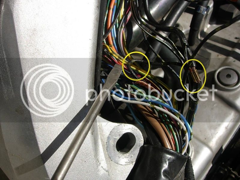
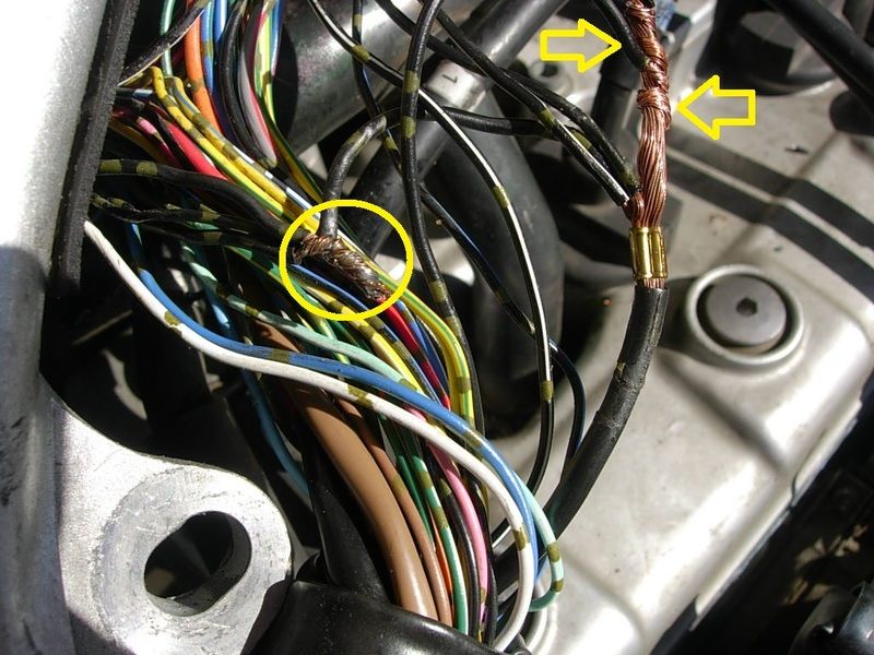
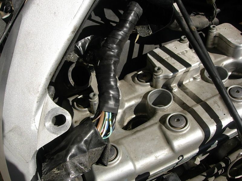
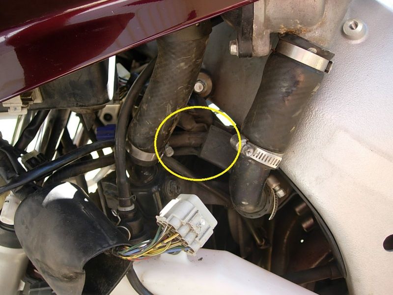
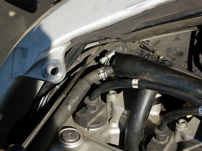
Circle shows the little chute where this section of 'T" gets pushed up into to gain slack in the engine compartment.

D_zpstibkxg27.jpg


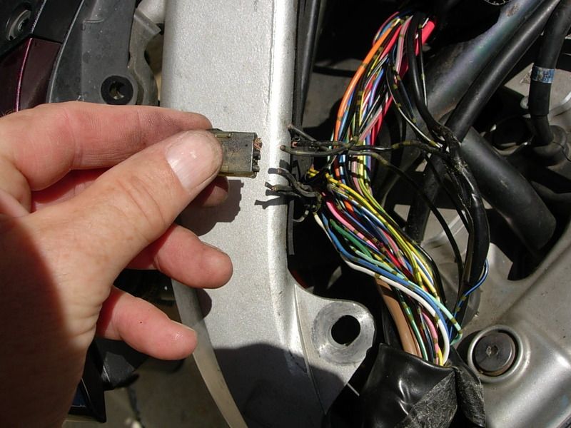
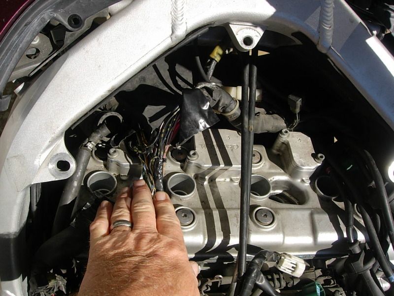
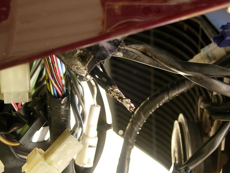
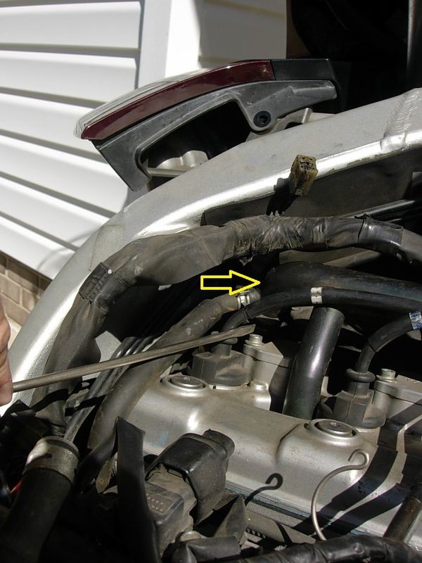
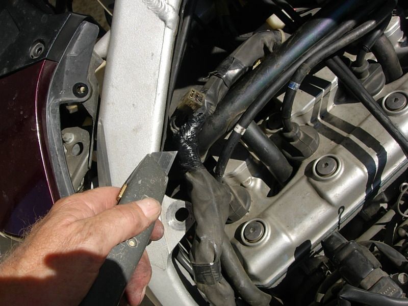
Screwdriver points to the object of my desires- the main wiring harness- to be pulled up. You can see the burned S4 spider on the right.

E_zpsoovvat2j.jpg


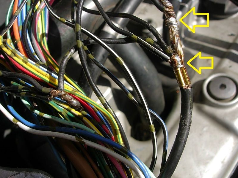
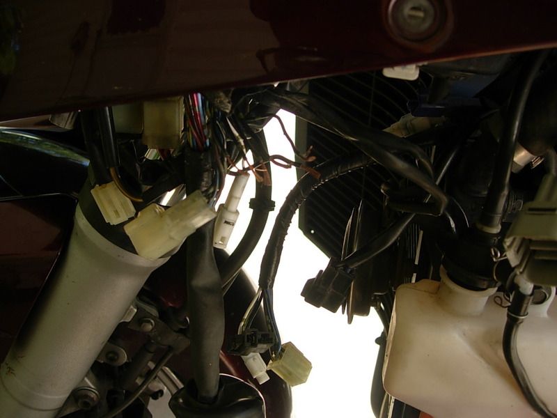
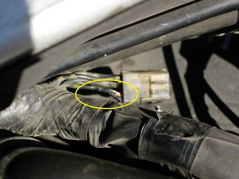
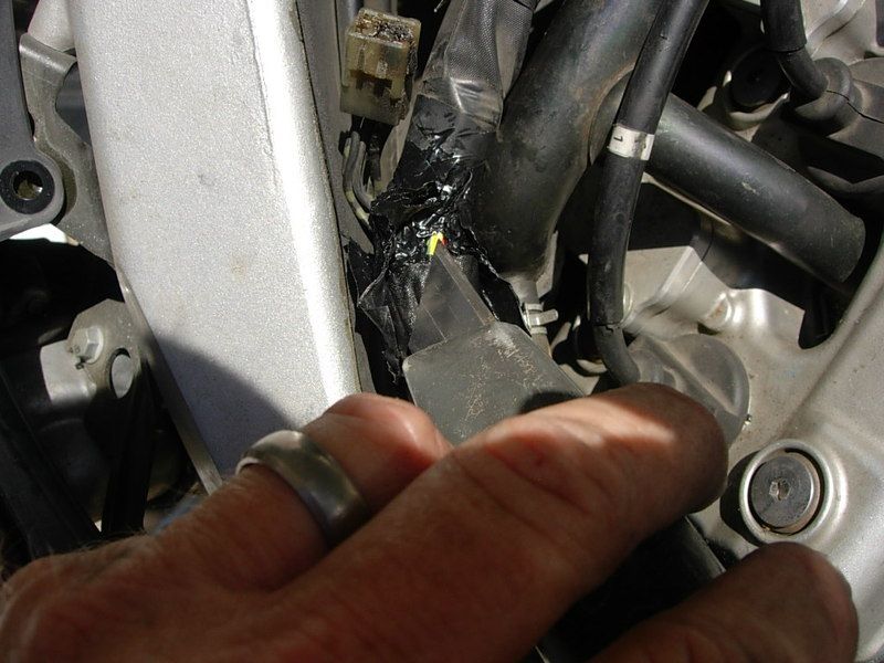
And the offending wiring in the S4. I later learned that this one small wire carries all the current collected in the spider back to the main ground wire. Also note- the straight sections of harness are covered with a folded wrap like a sticky note folded together with the sticky glue holding it closed. The 'T' section is plain ol' electrical tape.

L_zpsiwhnevoz.jpg


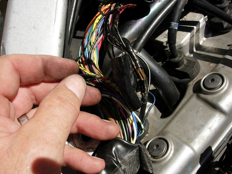
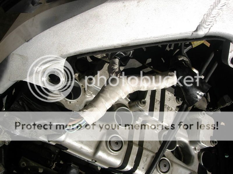
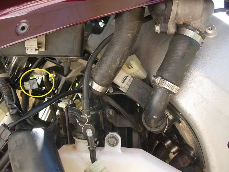
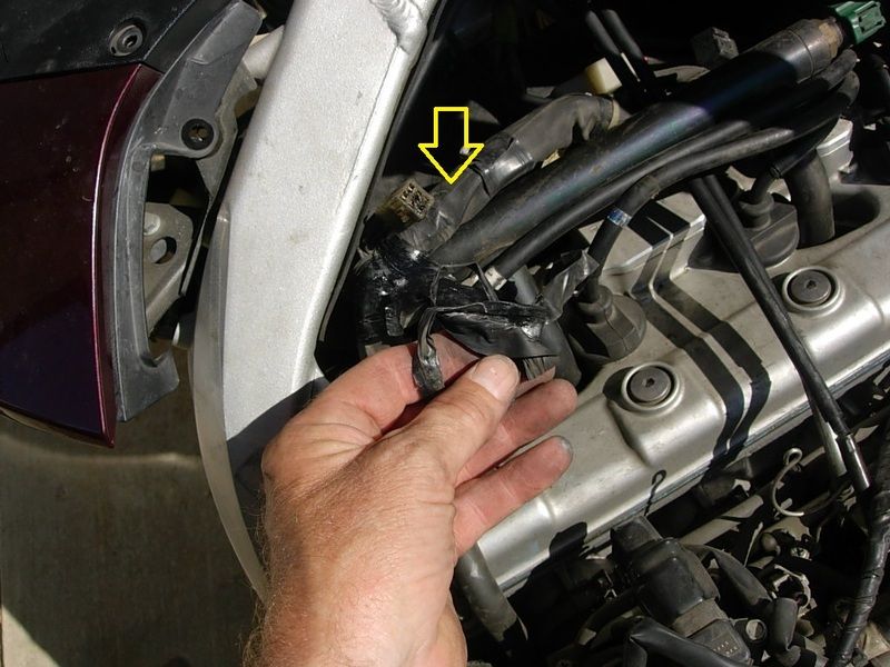
The arrow shows the coolant hose clamp removed to gain a little room. In this pic, by pushing up from the bottom and tugging up from the top you can see the harness starting to cooperate.

M_zps7zzcizic.jpg


Q_zpsllyasfek.jpg


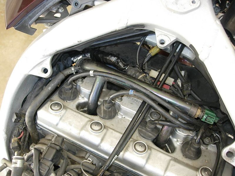
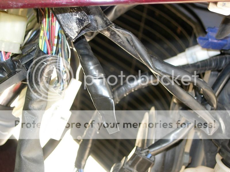
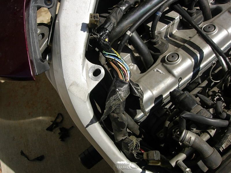
And now time to carefully unwrap

P_zpseoktx5br.jpg


R_zps0dsirvla.jpg


S_zpsbih22lxt.jpg


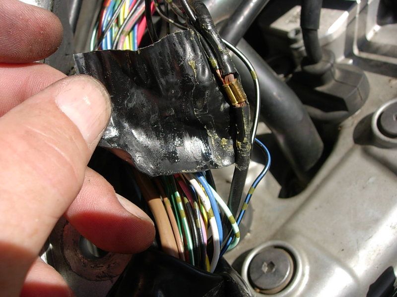
Once the tape is removed you can see what I meant about the sticky note-type cover

T_zpsngfrxvof.jpg


You know Russ, if you'd paint that thing a decent color, then you wouldn't have these issues.

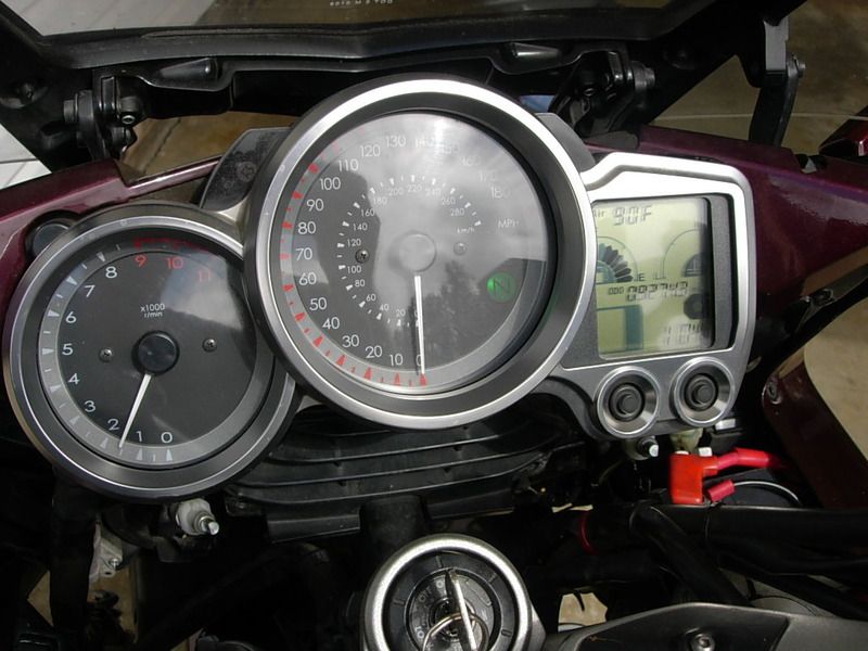
Oh hell no! Having these issues is one of the benefits of owning the bestest color FJR ever!

 
Last edited by a moderator:
Once untaped/unwrapped you can see there's a lot of wire to work with. See the electrical tape on the big black wire on the right? That's the main ground wire.

V_zpspq8li8ax.jpg


Unwrapping it exposed a crimp connector with small wires from various places.

W_zpsi6dfbiqq.jpg


X_zpsu2ai7tms.jpg


Circle on right is crimp connector. Circle on left- curved wire- is the single wire that carries all the current from the spider back to the main ground wire. I twisted together that one wire with the 3 coming up from the bottom and soldered those 4 wires together

Y_zpssvtviyyq.jpg


Left circle shows wires 4 wires soldered. The remaining 2 wires form the spider: I stripped back some insulation from the main ground wire, twisted the 2 wires onto it and soldered. I also tinned the crimp connector and other wires connected there.

Z_zps9gzrekvn.jpg


ZZ_zpsy2op6tpy.jpg


And voila!! Bikes runs. No hiccups yet!!

ZZZ_zpsr49vj0w4.jpg


----------------------------------------------------------------------------------------------------------------------------------

So that's that. Except it's a complete PITA to attempt to re-wrap/tape the harness this way. There's simply just not enough room. So the plan is to drain the coolant and remove the coolant pipe. And since I'm going through all this, while I'm here I'm going to do the S5 (coolant sensor area) and the S6 (glovebox area) spiders the same way. I'll take pics but I don't see any need to post them unless someone wants to see them.

 
Good job! As good as Yamaha seems to be with the design of most of the FJR mechanical parts, I'm not impressed with their engineering and design of the electrical. And with the increased emphasis on using mare and more digital controls and circuits I'm just wondering if more electrical type problems will not start appearing on the Gen 3 and later bikes. Kinda reminds me of the old Lucas electrical systems on the British cars of yesteryear! I wonder is BMW has similar electrical gremlins with their newer bikes?

 
We never got that aggressive with Vic's harness when we worked on his S4. I would loved to have had a little more slack.

Cutting the harness close to S4 us nothing. Didn't have the balls to tear up that much harness in the motel parking lot.

Regular size tools are too big to fit in the hole.

I'd be more adventurous at home with full inventory of tools and supplies.

 
I am wondering if I set myself up for a Bite. This summer, I set up my Gen III with trailer wiring. I installed a fused positive wire from the battery and a return ground followed by installing a 4 relays (R turn, L turn, brake, & tail lights). I have only used it a couple of times with no issue. Could the realys add enough load to lead to an issue?

 
I am wondering if I set myself up for a Bite. This summer, I set up my Gen III with trailer wiring. I installed a fused positive wire from the battery and a return ground followed by installing a 4 relays (R turn, L turn, brake, & tail lights). I have only used it a couple of times with no issue. Could the realys add enough load to lead to an issue?
No.
I agree with mc- no, b/c it sounds like your additions are connected directly to the battery.

 
Alrighty then, back to MY thread since it's MY spider bite and I'm the only one that matters
tongue.png
. Ha!!

So, what I've learned here is that if you're going to cut out and solder at the S4 spider, save yourself the hassle. Go ahead and drain your coolant and remove the dang coolant pipe. You'll be glad you did it in the beginning instead of the middle like I did.

Enough pics were marked previously you should see here that I've removed the coolant pipe to gain access room all around the wire harness. You actually gain a lot of room by taking the pipe out so just do it! Note the big hose straight above my ring finger, opening staring right at us. That hose goes down and bends left as we see it here. Pushing it down and pulling out from the bottom really helps gain room to work, too.
aa_zpspwype9wu.jpg

cc_zpsaowvufeo.jpg

dd_zpsyegz68n4.jpg


And then everything topside reassembled. Note- the coolant pipe cap screws are m6-1.0. I dropped one and had to to fetch another. It's down in the bowels of the engine somewhere below the throttle bodies. Who knows, maybe it'll fall out someday.
ff_zpstfrex4rz.jpg


I then moved around to the S6 spider. Unwrap, blah, blah, same as before. Cut, solder and wrap up.
hh_zps8z4udwyv.jpg

ll_zpsutyt6dfc.jpg

mm_zpszgngad63.jpg


Refill with coolant, put the plastics on etc., etc. In all not a bad job if you take your time and take lots of pics to refer back to. Only dropped and lost that 1 screw. Had no leftover parts or fasteners. Plus I used this snap lid type box with movable dividers for screws, rivets, etc. Once you get in the habit of re-snapping the lid every single time you open it, it doesn't matter how many times you drop it things stay put and nothing gets mixed up. Please don't ask how many times I dropped, kicked or swore at this poor box.
bb_zpscyl2ckge.jpg


So that's it. Hope someone somewhere someday is helped by all this. Over and out.

 
I'm amazed that Yamaha hasn't been hammered for this absurd problem.

If they built cars and did this crap they'd be mercilessly attacked by the media.

Low volume recreation products don't move the needle it seems. Nobody of importance is paying any attention.

 
I'm amazed that Yamaha hasn't been hammered for this absurd problem.
If they built cars and did this crap they'd be mercilessly attacked by the media.

Low volume recreation products don't move the needle it seems. Nobody of importance is paying any attention.
Send an email to a Yamaha President with a link to this Forum thread. Yamahas are well designed IMO...but they are screwing the pooch here with these spiders/whatevertheyarereallycalled.

 
Very nice job, thanks for the detail and pics.
I think if I were ever forced into doing this I would finish the job with Eastern Beaver's Sumitube W3B2 (or something like it) YMMV........
No need the way I did it:

1 layer of Scotch 33+ electrical tape, glue out;

1 layer of Scotch 23 rubber tape;

1 layer of Scotch 27 glass tape;

last layer of 33+, glue in.

water proof, temperature proof, extremely abrasion resistant, looks pretty too. What more is there?

------------------------------------------------

...deleted for politeness sake

 
Last edited by a moderator:
Very nice job, thanks for the detail and pics.
I think if I were ever forced into doing this I would finish the job with Eastern Beaver's Sumitube W3B2 (or something like it) YMMV........
No need the way I did it:

1 layer of Scotch 33+ electrical tape, glue out;

1 layer of Scotch 23 rubber tape;

1 layer of Scotch 27 glass tape;

last layer of 33+, glue in.

water proof, temperature proof, extremely abrasion resistant, looks pretty too. What more is there?

------------------------------------------------

...deleted for politeness sake
The main reason I like heat shrink, especially the internally glued stuff, is that it provides good mechanical support, which could be useful in keeping the joint together...............
There's no mechanical stress on the joint. All the wires except the grounds are straight runs and there's plenty of slack in the grounds. Besides, the various tapes reside in my toolbox, heat shrink does not. To each his own I guess, there's places I prefer heat shrink, this is just not one of them.

 
Last edited by a moderator:
I'm amazed that Yamaha hasn't been hammered for this absurd problem.
If they built cars and did this crap they'd be mercilessly attacked by the media.

Low volume recreation products don't move the needle it seems. Nobody of importance is paying any attention.
Send an email to a Yamaha President with a link to this Forum thread. Yamahas are well designed IMO...but they are screwing the pooch here with these spiders/whatevertheyarereallycalled.
...the ground joint connector...

 
... with these spiders/whatevertheyarereallycalled.
...the ground joint connector...
The Yamaha Workshop Manual for my Gen 3 Mk 1 (2014) calls these a "Joint coupler" as a generic name, used in many more places as well as a few ground connections. So I suppose, when used in the Gen 2 ground application, we might call it a "Ground joint coupler".
"Spider" has always been a bad name since the Gen 2 ones only have 6 legs. Unless you are in the habit of pulling legs off spiders.

On my Gen 3, most are identical to the Gen 2 ones, however some have different numbers of legs; I've not seen one of the odd-balls in the flesh yet, so I don't know their format.

 
deleted. some kind of weird shit happening in internet land .... or maybe just in my own brain. Spider connection must be corroded near my cerebellum.

 
Last edited by a moderator:
Wish I could see the pics. Its seems photobucket is not displaying them.
In case anyone is interested, thanks to PhotoBucket, I took some time to re-create my posts and pics in pdf format and uploaded them to my dropbox acct. Below are the links, split it into 2 pages for ease-of-conversion processes, so each link contains about 1/2 of the original thread, pictures included. When you open a link you should see a download button top right for that, printing, etc. Hopefully this will continue to assist folks in the future now that pics are see-able again. I understand it's not in the best layout, sorry about that, but my main concern is to get the info back out there somewhere where folks can see it.

page 1 https://www.dropbox.com/s/lp9tr6zyoplge99/Ground%20Spider%20Thread%20FJRFORUM%20pg%201.pdf?dl=0

page 2 https://www.dropbox.com/s/rg91hx829rpvd9q/Ground%20Spider%20Thread%20pg%202.pdf?dl=0

 
Hi all! I hope everyone had a great holiday and having a safe new years celebration so far! Personally, I am very much looking forward to putting 2022 behind me.

Anyways, on to my question.. I know this is an older thread and I apologize for bring it back up. I am having trouble with this dreaded spider bite...

I have a 2010 FJR and have been able to locate a few of these grounds so far. However, going off of the schematic that was posted earlier I haven't been able to find a couple of the other ones. The pictures I've taken are of the ones I've found so far, I couldn't tell you which one is which but I plan on doing some soldering so I thinking it won't matter as much. I've scoured the remaining areas of the front cowling and all around that area and there aren't any more, at least not that I can tell. Does anyone have any advice on where the others might be, if they even exist?

I had the exact same issue as the OP, headlight stopped working, high beam light came on, windshield stopped working... I'm thinking the culprit is the ground under the LHS glove box. However, in my inspection of everything I came upon this connector(see photo) that had about a cup of water sitting in the plastic insulation cover and the connections look gross. I'll be replacing them with some deutsch connectors. Perhaps that was the problem all along?

I appreciate any thoughts you all have! Thanks and hope everyone has a great new years celebration so far!
 

Attachments

  • 20221231_154250.jpg
    20221231_154250.jpg
    1 MB · Views: 0
  • 20221231_154236.jpg
    20221231_154236.jpg
    1.2 MB · Views: 0
  • 20221231_154228.jpg
    20221231_154228.jpg
    1.2 MB · Views: 0
  • 20221231_150105.jpg
    20221231_150105.jpg
    2.2 MB · Views: 0
Top