Soltek Aux Lighting install

Yamaha FJR Motorcycle Forum

Help Support Yamaha FJR Motorcycle Forum:

This site may earn a commission from merchant affiliate links, including eBay, Amazon, and others.

skyway

Well-known member
Joined
Jun 15, 2005
Messages
2,507
Reaction score
-44
Location
Sonora, CA
There's been a lot of discussion about "the switch" that I use to control the Soltek lights. Here's an explanation of how and where it's located on my bike.

First the location:

IMG_2256.jpg


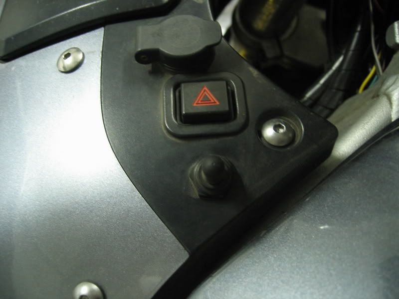
You will notice that the switch is mounted on the lower area of panel "A" on my bike. It is a (center off) 3 way single pole heavy duty toggle switch. I purchased it from True Value Hardware along with the rubber boot accessory that you see in the photo that's covering the steel toggle switch.

I choose to wire the switch in-line with the FJR hi-low beam switch, because I don't want to police 2 separate switches at night when dealing with my hi and low beams and the aux. lights. This switch is tied in with the factory hi-low beam switch and gives me 3 different options of control.

The 3 way switch serves to give me the following features:

  • In the center position, my aux.(Soltek) lights are always off, regardless of the position of the FJR hi-low beam switch on the handlebar.
  • When the switch is toggled in the back position the aux.(Soltek) lights will fire off at the same time as the stock high beams with the switch on the handlebar.
  • When the switch is toggled in the forward direction the aux.(Soltek) lights will fire off regardless of the hi-low beam switch on the handlebars.
Link to Bin-O-Facts description and photo's of said switch. Toggle switches and Boot covers (Bin-O-Facts)

Now to tie this all together with the factory wiring harness.

NOTE: I am using a single pole double throw switch and not a double pole double throw switch as shown in the diagram. The diagram and explanation will work with a single pole double throw switch.

Explanation courtesy of Warchild.


* Stock switch refers to the high beam switch on the left handlebar.

piaa_switch.gif


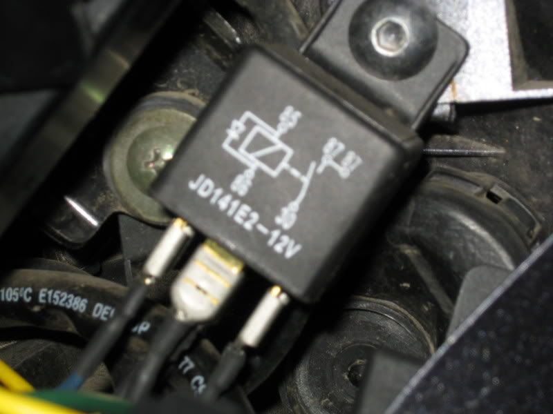
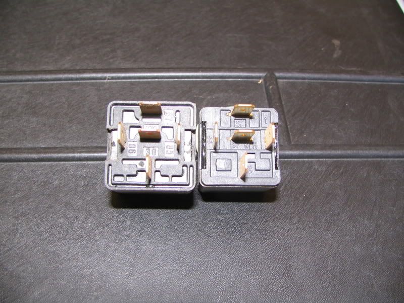
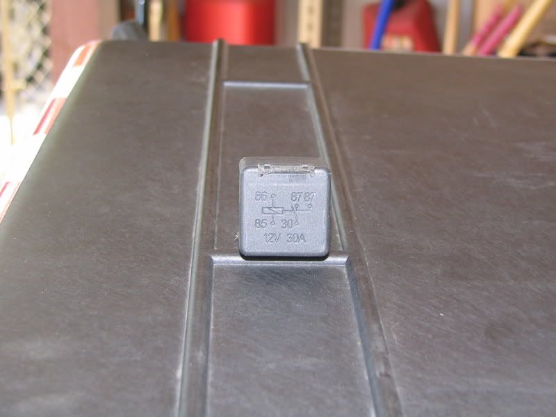
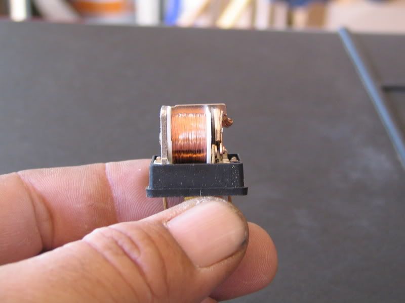
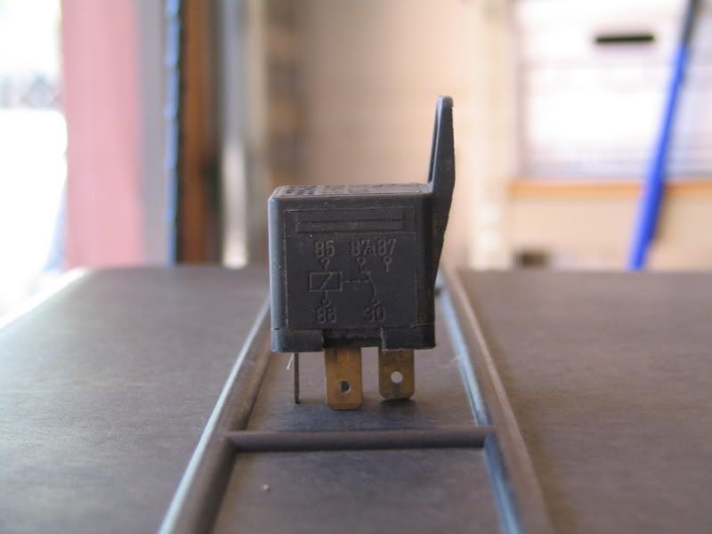
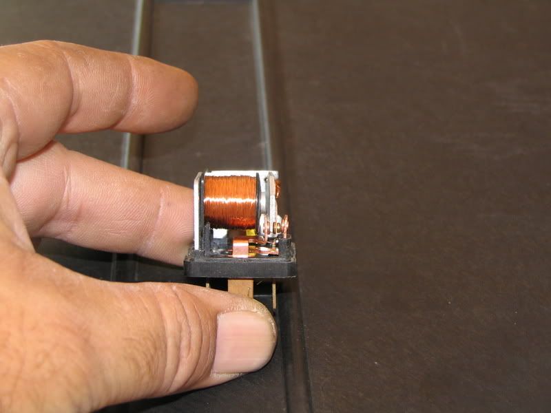
I will assume you have a 4-terminal relay to power the Solteks, rated at 25-amps or better

Where is says "PIAA relay" above, you will connecting that wire to the positive input of the relay powering the Solteks... say terminal #86.

Therefore, terminal #85 of this relay is connected to ground (-).

Terminal #30 is connected to the heavy-duty 12-gauge wire that is INCOMING power (+) to the relay. This incoming wire is fused by a 25-amp fuse (though truthfully, you can get away using a 20-amp fuse just fine).

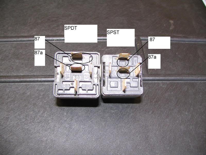
Terminal 87 is therefore your OUTGOING positive wire (+) that connects directly to *both* red wires on the Solteks.

Regarding your SPDT switch:

The top pole is connected to any *switched* (+) power source. Thus, there is power at this pole only when the ignition is on.

That bottom pole, I am guessing you want to connect to the one of the high-beam lights (positive (+) wire, of course).

WHEN WIRED AS I'VE DESCRIBED, the effect is as follows:

1) When toggle switch is thrown "upward", the Solteks come on **regardless** of the status of the high-beam or low-beam. Doesn't matter which (hi or low) is lit up at the time.

2) When the toggle switch is left in the center, the Solteks do nothing. They remain unlit at all times.

3) When the toggle is thrown downward, the Solteks light up only when the stock high-beam switch is engaged. They extinguish when the stock headlight switch is thrown back to its low beam setting.

If there are any further questions regarding "the switch" please respond below and I'll try to answer them.

 
Last edited by a moderator:
I put my switch in a temporary spot for the WFO trip, but it'll settle in to the location of the Euro "flash to pass" switch.

At one point on the way home, my finger was lazily out of position and I couldn't get them shut down for an oncoming big rig. Poor guy probably thought he was having a close encounter of the third kind.

My point is, the switch needs to be in a place where you can get to it quick and without looking, and that should be the highest priority for choosing a location. Also, it should be of a type that can easily be turned to off, like maybe off being at one end or the other, not in the middle of the range, if possible. YMMV.

 
Last edited by a moderator:
Also, it should be of a type that can easily be turned to off, like maybe off being at one end or the other, not in the middle of the range, if possible.
Toe,

This is a good idea, but have you actually found a switch like this? I don't remember ever seeing 3-way toggle switches other than center-off.

-sam

 
Also, it should be of a type that can easily be turned to off, like maybe off being at one end or the other, not in the middle of the range, if possible.
This is a good idea, but have you actually found a switch like this? I don't remember ever seeing 3-way toggle switches other than center-off.
No, and I don't doubt that they're not available in that configuration.

I saw a pretty trick switch setup at WFO (surprise!). There was a box with a couple of switches mounted to the inside of the left V-Strom handguard, so an extended finger could operate them easily. Not always convenient to take a hand off the bar....

I'll just be wiring mine to be independent of the other lights, so I can use the switch I already have in place.

If I were running OEM headlights, I would figure out a way to have them shut down when the Solteks were switched on, to save that useless 110 watt additional draw. With my current setup (one HID headlight on), the Solteks only draw about 15 watts over stock headlights.

 
One change I would suggest on your wiring is your assignments of pin 87 and 30.

If you put +12V on pin 30, and the relay has a pin 87A (not all relays do), then pin 87A is charged and waiting for a short while the lights are off. If you put the +12V to pin 87 and the load on pin 30, then everything stays contained inside the relay.

It's just good practice for all relay installs.

 
If you put +12V on pin 30, and the relay has a pin 87A (not all relays do), then pin 87A is charged and waiting for a short while the lights are off. If you put the +12V to pin 87 and the load on pin 30, then everything stays contained inside the relay.
On mine (5-pin relay), I think I connected pin 30 to the 12V supply, then 87 & 87A one each to a load positive. As I understood the diagram printed on the relay, 87 & 87A were both off until the relay was energized, and both hot once the relay was switched on. And it works like I hooked it up, with no bare pins exposed.

Also, I put a single 20 amp fuse in line between the battery and pin #30, in case anything bad happened anywhere downstream.

 
Last edited by a moderator:
Not quite. On a 5 pin, SPDT relay, pin 87a is a NC switch and is connected to pin 30 when the relay is not energized. Pin 87 is a NO switch that is only connected to pin 30 when the relay is energized.

Thus, if you have pin 30 connected to +12V, and the relay is off, pin 87a is energized with nothing connected to it. In other words, you have an open source of +12V just waiting for a short. That's why pin 30 should be connected to the load in a single use application.

However, if you are going to use both pins 87a and 87, then it doesn't matter. For example, the a typical car's headlights. You know low beam is always on, so you have low beams connected to pin 87a, thus they are on when the relay is not triggered. When you hit the high beam switch triggering the relay, power switches from 87a (NC) to 87 (NO) and you now have high beams, and the low beams are turned off.

Of course, all of this is moot if you do what Ian recommended originally and used a 4 blade relay (NO only). The confusion comes in, and the only reason I mention it is, when you use a 5 blade relay (SPDT) in a 4 blade relay application. It is good practice to put the load on pin 30 and the power to pin 87. This avoids the potential for an unwanted short by having a constantly powered pin 87a

 
Last edited by a moderator:
OK, here's the diagram for the relay I used from NAPA A/P (says it's a SPST relay).

I don't know much about SP's, DT's, etc...so I just used the picture.

FakeRelay.gif


So, neither pin (87, 87A) is hot until they both are in this case. Otherwise, one of my Solteks would always be on.

Looks like we're comparing apples to oranges (SPDT to SPST). :blink:

 
OK, here's the diagram for the relay I used from NAPA A/P (says it's a SPST relay).
I don't know much about SP's, DT's, etc...so I just used the picture.

FakeRelay.gif


So, neither pin (87, 87A) is hot until they both are in this case. Otherwise, one of my Solteks would always be on.

Looks like we're comparing apples to oranges (SPDT to SPST). :blink:
Not really apples to oranges, what you have diagrammed is a SPDT relay. Pin 85 and 86 trigger the relay, pin 87a is NC (normally closed) which means it is connected to pin 30 when the relay is at rest. Pin 87 is NO (normally open) which means it is only connected to pin 30 when the relay is triggered.

If you have a relay that is labeled as pin "87a", it is a normally closed contact with pin 30. That is the industry standard. Do a google search on "Pin 87a" and you'll see what I mean.

I am not sure how you have your lights set up, but on a standard 5 blade automotive relay, pins 87a and 87 will never be connected to pin 30 at the same time.

This is a common problem/mistake, I have bought the relay TC is showing wanting a SPDT relay assuming all 5 pin relays are SPDT... THEY ARE NOT!

What TC is showing is a 5 pin SPST relay where 87 & 87a are tied together and both normally open contacts!

There are also 5 pin SPDT relays where 87 is normally open and 87a is normally closed.

 
Last edited by a moderator:
This is a common problem/mistake, I have bought the relay TC is showing wanting a SPDT relay assuming all 5 pin relays are SPDT... THEY ARE NOT!
What TC is showing is a 5 pin SPST relay where 87 & 87a are tied together and both normally open contacts!

There are also 5 pin SPDT relays where 87 is normally open and 87a is normally closed.
I've never seen that, but would love to. Because, if it's labeled 87a, it should by a NC circuit based on the industry standard. If it is labeled 87, then it is NO. Having two 87 pins I can even understand, but in all my years around relays, I have never seen a pin 87a that was a NO contact. In all the web research I've done, I still have yet to see one too, so if you have a link, I'd love to see it.
I'll dig in my garage, I'm 99% sure I have a spare, and mail you one.

 
Just to clarify, I'm not trying to start any type of disagreements or anything. This started as what I thought would be a productive suggestion of having the load connected to pin 30 to prevent the opportunity of a short by having pin 87a being live with nothing connected to it.

I certainly am not suggesting I know everything about relays, but it has been my experience (and I do have quite a lot of experience with this) as well as everything I can find on the web, that the industry standard for pin 87a is that it is a normally closed switch connected directly to pin 30 on SPDT relays when the relay is at rest (not powered).

What I am interested in, is if there is another 5 blade relay where both pins are connected to pin 30, is how it is labeled.

 
What I am interested in, is if there is another 5 blade relay where both pins are connected to pin 30, is how it is labeled.
Well, I'm not pulling mine back out just to take a picture of the diagram on top of the case. However, IIRC, there was an 87 and an 87A, and they must be both normally closed, or one of my Solteks would always be on, as I connected one to 87(?) and one to 87A(?).

Rogue should be able to post a pic, if he has a spare one lying around.

The diagram I posted above shows both 87 & 87A contacts open, and tied together when the switch is closed.

 
I just got home and grabbed one of these, the schematic on top of it shows two 87 terminals but the manufacturer (no name on the relay) uses the same bottom plastic piece on their SPST & SPDT relays so the pins are numbered 87 & 87a even though they are both pin 87.

 
As luck would have it, the diagram was pointing out from the naked innards of the bike. There's no 87A, just two 87's, both NO and tied together. Perfect for the Soltek setup, IMHO, but still conforming to "industry standard". Ignorance is bliss, and all is well.

Relay.jpg.jpg


That reminds me, I still have to wrap those terminals, once I get the right wires (for the new switch) hooked to them.

 
Lets see how these pics turn out:

SPDT on left, SPST on right

IMG_3132.jpg


Schematic of SPST

IMG_3124.jpg


Guts of SPST

IMG_3130.jpg


Schematic of SPDT

IMG_3127.jpg


Guts of SPDT

IMG_3129.jpg


That's what I suspected. The dual output when relay is triggered is not labeled as 87a, they are both labeled as 87, which would conform to the industry standard.

IMG_3124.jpg


Which goes back to my original point. If you have a 5 blade relay that has an 87a, it is not wise to hook power up to pin 30 if you are using the relay in a single use application. Doing so invites a short.

 
Last edited by a moderator:
That's what I suspected. The dual output when relay is triggered is not labeled as 87a, they are both labeled as 87, which would conform to the industry standard. Which goes back to my original point. If you have a 5 blade relay that has an 87a, it is not wise to hook power up to pin 30 if you are using the relay in a single use application. Doing so invites a short.

Except the pins on both are labeled 87 & 87a:

IMG_3132-notes.jpg


Top