Broken Penske Clevis.

Yamaha FJR Motorcycle Forum

Help Support Yamaha FJR Motorcycle Forum:

This site may earn a commission from merchant affiliate links, including eBay, Amazon, and others.
Sounds like they could use a little design modification. Here we are thinking that we were making mistakes on the install and it is at least partly due to their inadequate design.
Yeah, you can ignore minor stuff like this and other routine maintenance stuff and get away with it for a long time. But when it bites you in the ass when you're on the road in east BFE, it can be a major PITA. You buy your ticket and you take your chances.

Only a little Fred?
smile.png
Hell there are so many things wrong with this design it is a wonder more have not broke. And the issue is still unresolved. This is going on my watch list just like checking the air in my tires.

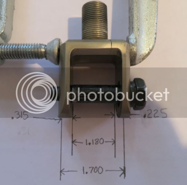
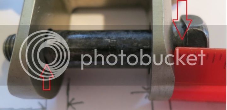
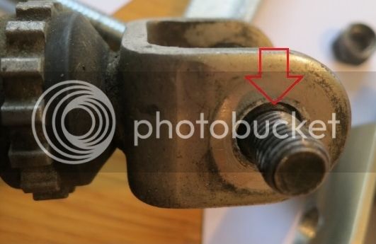
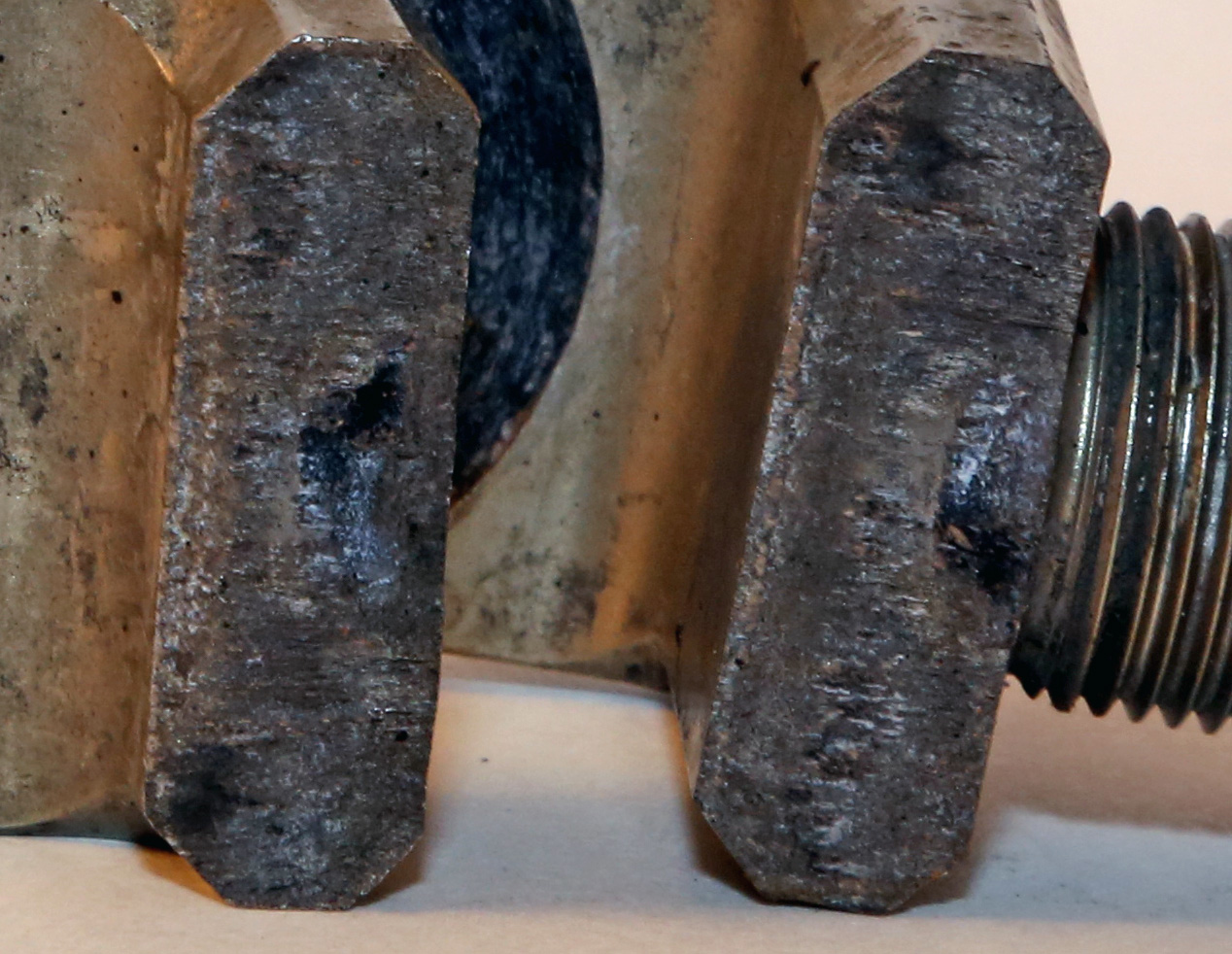
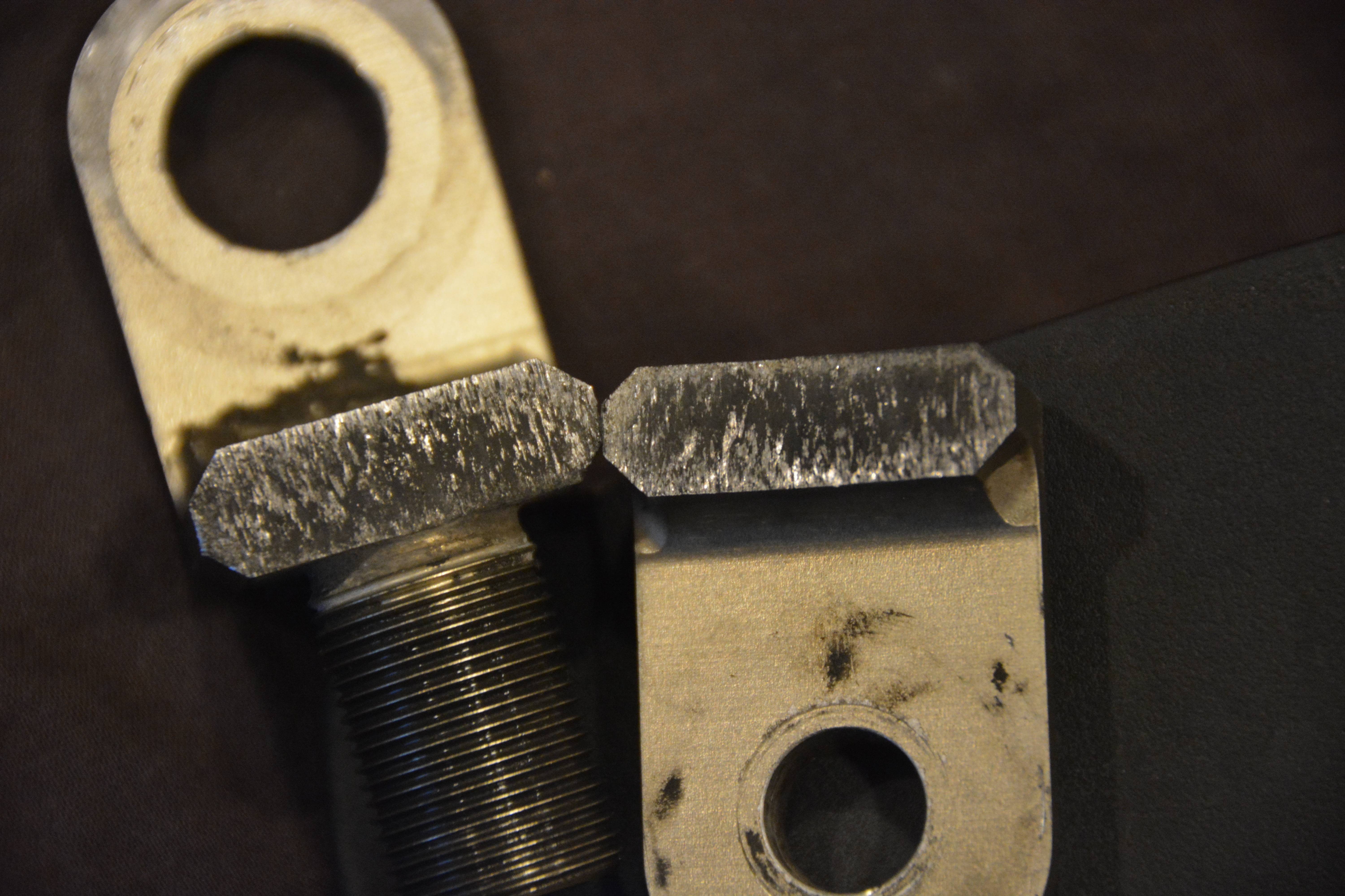
A 650 lbs motorcycle with an aluminum rear shock clevis where one side of the clevis only has 41% engagement with the minor diameter of the bolt.
weirdsmiley.gif
Never mind the bolt is about 3/16 of inch too short, after all didn't we all learn a good design is the bolt shall have at least 2 threads above the nut? Nuts!

 
Last edited by a moderator:
...3. Yamaha stock bolt is too short as two threads do not protrude the nut when tightened. This can lead to over torquing. Furthermore the Yamaha stock nut locking feature is at the end of the nut. I am going to look for a a nut with a nylon locking. Generally the lock feature of nylon lock nut engages sooner than the lock feature of the factory nut. Hopefully I can find one and add some blue locktite.

...
I would not suggest using Loctite on a Nylock nut. It should not be needed and the Loctite might interact with the plastic - I know it will embrittle ABS plastic and some other polymers. Even if it didn't degrade the nylon, I don't think it would stick well anyway.

Otherwise, good information from Penske!
Good info on the Locktite. The nut is a M10 1.25 thread pitch. These are hard to find. I did use a very thin washer to increase the engagement of the lock feature on the stock nut. Perhaps I will just stick with the Locktite. The nut only needs to stay in place so snug is good and more than snug is bad. Certainly a situation where more is not better.

 
Again I point out that there are alot of folks , myself included, using Ohlins rear shocks on the FJR and I have never heard of a clevis failure on them. Might want to look at that design for ideas.

 
Well I am not excited about the fact that it bends, although as mine is non-adjustable - and doesn't have that threaded stud - I guess it's less likely to fail. I will be putting loctite on mine..

 
Been reading this thread with interest as KrZy8 gets ridden nearly daily over 6 miles of nasty stutter bumped, whooped out, pot-holed dirt road at speed daily. Checked my clevis carefully and no signs of breakage. Last linkage lube was years and multiple 10's of k's ago.

 
Actually 186 posts, including yours and mine. ;)

And in all of these posts, with as many guys that are reporting broken clevises on their Penske shocks, we still don't have measurements of the critical dimensions of the clevis and the stock shoulder bolt like I showed in my sketch here, and like Rayzerman made on the Race Tech shock's clevis in his post here

My original accusation was that the breaks were caused by the wrong bolt being used, which puts lateral tension on the clevis' yoke, that eventually leads to failure of the yoke. This was true for sure in those cases where the guys moved from Wilbers shocks to Penske shocks and unknowingly re-used the Wilbers shoulderless bolts.

It now appears that even when using the stock Yamaha shoulder bolt it results in a higher than expected part breakage rate, and the current hypothesis is that the shoulder of the stock bolt is not long (wide) enough for the thickness of the Penske clevis, resulting in some lateral tension on the yokes (though less than what the Wibers bolt caused).

My son has my '05 w/ a Penske on it up in Vermont these days, or I would have pulled the parts and measured them myself by now. If someone with a Penske shock could just measure the thickness of the clevis yoke side at the large diameter hole we would be able to figure this thing out definitively.

If it turns out that they are all side loaded this way by design default, then any one of them could end up broken at pretty much any point in time, even those guys that just got brand new clevises from Penske to replace their old broken ones. Personally, I'd like to confirm the root cause as I'd fix it somehow before it broke on my son's bike, as I have an interest in keeping him safe. Is this thread really "pointless"?

 
Thanks guys - I installed my 8975 back in May.. Using the bolt that came off my stock shock. I am going to look at this closely this weekend.

 
I hope you passed this info along to your son and he is keeping an eye on it. The good news is that it doesn't seem so detrimental a situation even if it is broke. Folks have ridden with broken clevises for quite a few miles. I seriously can't believe Penske is just giving you the same part back after you broke it. There needs to be a stop on production and a redesign done. If your buying a used Penske shock and don't use the correct bolt I wouldn't blame Penske for that.

Now, 188
winksmiley02.gif
Home today.

Dave

 
Yep, that's a crappy design. They can easily beef up that radius. That's just amateur stuff and I'm pretty sure they didn't subject it to the loads it would be sustaining for 100K miles.

Just my $.02

 
Funny thing, when I did my penske install in June, I posted here :

https://www.fjrforum.com/forum//index.php/topic/168593-penske-install-question/?p=1318915

(Post #9, I said "Question about the bottom clevis though, that fit pretty loosely, is the washer supposed to go inside the clevis? I torqued it down to specs, but I feel kind of funny about this havin seen a cracked clevis recently on here (I think) "_)

That gap I noticed strangely disappeared once I torqued that nut onto the bolt.. (Magic, right?)

So I am obviously going to have a problem someday soon. I've got about 2500 miles and counting since then.

 
Fred W asked for some photos and dimensions. So here you go.

Here is the clevis and the bolt. I will refer to the large and small diameters of the bolt and now you know what I mean.

1-Pic_zpsz4ua7x6a.jpg


I used a clamp to hold the clevis together to obtain these measurements.

2-pic_zpshafitjus.jpg


I have two issues with using the stock Yamaha bolt. Penske does not have a bolt built for this application and they recommend using the stock bolt.

Issue One:

The arrow on the left shows the chamfer on the bolt's small diameter. The small diameter is just starting to penetrate the left yoke hole. The left yoke width is .315 inches.

The arrow on the right shows about .125 inches of bolt engagement remain. This means about .190 of the yoke is not supported by the bolt's small diameter. Only .125 inches if the small diameter is engaged in the the yoke the rest is filled by threads. I am concerned this could lead to rocking, especially of the nut is over torqued and bends the clevis yoke.

3-pic_zpsl4hai2nq.jpg


The stock shock clevis is shown in the next photo. You can see the small diameter of the bolt is fully engaged with the clevis. The arrow shows the bolt's chamfer.

4-pic_zps0vdtyopw.jpg


Issue Two.

The bolt is too short. This photos is without a washer. There is about one thread of bolt showing. There should be at least two threads. The can lead to over tightening and an unwanted lateral load on the clevis.

5-pic_zpsng3tr2lu.jpg


Other design issues include using the FSM torque values, the risk of putting a lateral load on the clevis and the lack adequate radius at the bottom of the threaded boss provides a stress concentration leading to fatigue failure.

 
Last edited by a moderator:
Since the thread is about Penske breaks...here are some high res pictures of the two failures I had. (You can click on each for even higher resolution).
First is the most recent failure with the two pieces in the picture. Failure is on the side with the big hole just barely into the thread barrel.

MWK02721.jpg


MWK02721b.jpg


My first failure I could only find one piece. Seemed to break closer to the threads and, interestingly, the failure is on the small hole side much closer to the middle.

MWK02720.jpg


MWK02720b.jpg


My recollection is that I tried my leftover Wilbers on both of these items and after the 2nd I thought I needed to use a shouldered bolt. With failure on the opposite sides...I wonder a little if it was that.

Remember too that mileage on each of these before failure was somewhere between 0 and 20,000-30,000 miles on a well loaded rally bike with fuel cell, luggage, and my big ass.
Another try at the high-res image..
OmlN923.jpg
Great images Ignacio, thanks.
By my partially trained eye, your second failed clevis appears to confirm what we've suspected: crack initiation at the intersection of the clevis and base of the threaded rod. Then the crack propagated with slow movement until about 15-20% of the cross section had cracked, and then it proceeded to a complete failure of the remaining area in relatively quick fashion (perhaps upon a single, sudden load).

Your first clevis failure shows similar by my partially trained eye, but appears to have took longer to fail. It appears the crack also initiated at the intersection of the clevis and base of the threaded rod, then proceeded slowly over time to about 40-50% of the cross section, then the failure completed in quick fashion. It appears this clevis is steel (rusting iron), or it was stored [after failure] near iron-based metal?

It also appears that the raw stock that the second failed clevis was made from (appears some kind of aluminum alloy) is very uniform, and also that there are indications of stored stresses at the machined surfaces (to be expected).

I also see some interesting scoring marks around the bolt holes. This indicates there's load twisting the clevis around the axis of the mounting bolt as the shock is compressing/rebounding. It appears the clevis-to-tang interface is dragging and perhaps that the bolted joint is adding to the stress at the notch.

The use of the word 'fatigue' many times throughout in this thread is not likely fitting. Stress induced crack propagation can be fatigue, but it is likely more simply that a momentary stresses in the part at that notch (between clevis and threaded rod) are higher than the material's Ultimate Strength. Fatigue is more complex than that--ie, 'fatigue' is not a necessary explanation for this failure.

Above is by my partially trained eye. I'll have a chance middle of next week to ask a favor of an expert.

As promised, I was able to have these images reviewed by someone expert in failures. The deduction is the same as I posted in post #132 (copied above).

A couple additional observations:

Iggy, your #1 failure took the longest to fail of any others shown in this thread. Your #2 failure took quite a while too, but not as long as your #1 failure. Many failures are almost instant (just as Fontanaman's post directly above shows).

In all cases, the crack initiates at the base of the threaded rod, at the notched interface to the flat area of the clevis. But what is apparent is that this crack is on the wrong side of the clevis. I'm assuming that the FJR's shock is in compression, and when the suspension is compressed, the shock if further in compression. If accurate, the surfaces of the clevis where the failure is initiating is in compression. Solely by forced loading (impact loading) stress cracks shouldn't form where they are forming if the stress is caused by suspension load impacts.
 
Bummer... all my typing that I'd added to the above post is gone! Grrr.

Give me a few minutes and I'll reproduce it...

 
Fontanaman

I thought that the "large diameter of the bolt" was supposed to fit into the hole on one side of the clevis. I think that's how it worked on mine. I can't go and look at it because I have the OEM shock back on waiting for a rebuild of my Penske (haven't gotten around to it yet). That would make the bolt long enough to prevent sideways clamping on the clevis. I am pretty sure that the hole on one side of the clevis is large enough to accommodate the shoulder and the other side is not.

Maybe I'm mis-remembering or maybe the hole just isn't big enough on the some of the Penske clevis???

The mystery continues...

 
Fontanaman
I thought that the "large diameter of the bolt" was supposed to fit into the hole on one side of the clevis. I think that's how it worked on mine. I can't go and look at it because I have the OEM shock back on waiting for a rebuild of my Penske (haven't gotten around to it yet). That would make the bolt long enough to prevent sideways clamping on the clevis. I am pretty sure that the hole on one side of the clevis is large enough to accommodate the shoulder and the other side is not.

Maybe I'm mis-remembering or maybe the hole just isn't big enough on the some of the Penske clevis???

The mystery continues...

The large diameter of the bolt fits inside the large clevis hole. The problem is when the bolt is completely inserted, the smaller diameter of the bolt is not supported by the clevis yoke, (issue one in my last post) and the bolt is too short - two threads do not protrude the nut (issue two in my last post). In one of my photos above I choose to show the bolt not completed inserted to illustrate the small diameter only engages into the clevis yoke .125".

A good start would be to have a bolt specific for this application. Better yet would be a new clevis, made of steel or stainless steel and an new bolt.

 
Last edited by a moderator:
I was able to get someone who's familiar with looking at fracture surfaces and he essentially confirmed my observations from post #132.

But a few additional and reinforcing observations:

Iggy, your #1 failure lasted the longest (cracked) of any shown in this thread. It is also very peculiar that it has iron-based oxides on it. Was it stored in a humid environment after failure, next to iron-based metals? Your #2 failure was shorter in life, but still lasted a while cracked. Many other's failures shown in this thread were very small cracks (or NO cracking) and sudden instantaneous failure of nearly the entire failure area.

TominPA, your image is a bit fuzzy, but it appears yours failed instantly with no initial crack (or with a crack so slight that it isn't discernable).

If the shock is in compression as installed (I assume that is accurate), the 'notch' between the base of the threaded rod and the flat area of the clevis is normally in compression. It is much harder to initiate cracks in the material from compression, so this clevis shouldn't be initiating cracks where they're initiating if the cracks are initiated by suspension load impacts. This suggests that either the rebound forces (as the shock re-extends) are amplified by the linkage design OR that the two sides of clevis are being pulled together when bolted (closing the 1.180" gap Fontanaman illustrated above). Pulling the two sides of the clevis inward puts tension in the metal at the notch in exactly the correct orientation to get the failures folks are seeing.

Add in any bolt shouldering mismatches (such as Fontanaman shows above) one side to the other, and only one side of the clevis carries loads, and that further amplifies the loads on the notch.

It appears most likely from these failures that the clevis bolt is pulling together the two sides of the clevis (even if only slightly), and that if bolt shoulders don't fit well to the through-hole sizes of the clevis, there are high chances of crack initiation at that notch between the threaded section and flat surface of the clevis..

Another observation is that the metal (whatever metal it is), shows it likely would benefit from an appropriate heat treatment to modify it's microstructure to be tougher. The columnar 'grains' (lined up along the shock's axis) are visible in many failures, illustrating that the material could be improved.

Whatever the actual cause, I'd be inspecting mine routinely if I had one.

Hope that helps.

 
I was looking at pictures and not reading everything. I wish I had the Penske on the bike now and I could look at mine for comparison.

 
In all cases, the crack initiates at the base of the threaded rod, at the notched interface to the flat area of the clevis. But what is apparent is that this crack is on the wrong side of the clevis. I'm assuming that the FJR's shock is in compression, and when the suspension is compressed, the shock if further in compression. If accurate, the surfaces of the clevis where the failure is initiating is in compression. Solely by forced loading (impact loading) stress cracks shouldn't form where they are forming if the stress is caused by suspension load impacts.
I'm going to have to disagree with you on the compression load, BakerBoy. That failure is not under a compression load. It's under shear and tension. The tension comes from the bolt squeezing the legs of the clevis together reducing the "gap" that Fred's been talking about. The shock itself is compressing up and down against the dog bone that's opposing it every step of the way. Those up and down forces are creating a massive shear load that causes the failure. The failure being vertical shows that it sheared off. A compression failure would be horizontal in this case and it's a completely different animal. To give you a visual, take any of the pictures of a cracked clevis, hold one piece in each hand, mate them and start rubbing them together one going up while the other is going down just like the shock would be doing. That's Shear! I don't wanna step on your toes, buddy. Just wanted to keep this thread accurate as far as the loads that we are dealing with on this issue. Let's continue, Please... :)
 
Lol, no not shear. The failure surface would be different than these failures. You should reread what I wrote as I am saying it is likely driven by clevis bolted joint design.

 
Last edited by a moderator:
Top