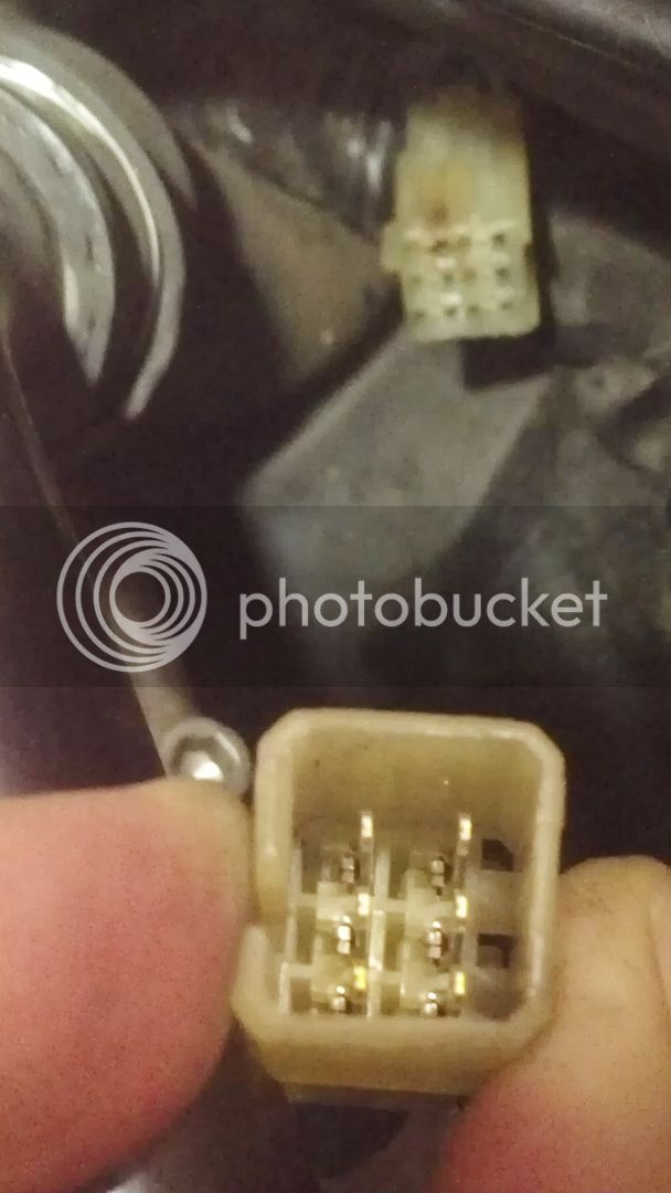
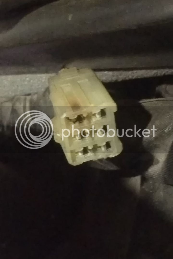
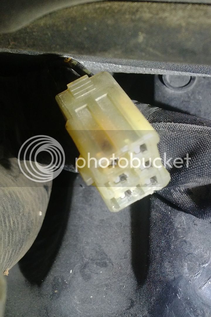
There are too many independent items not working for it to be the ignition switch, IMO. Usually the kind of oddball light combinations are the result of a bad ground. I do see that a lot of the problem items share a common ground at the meter assembly. This ground comes through non-spider connector #31 which is a rectangular 6 pin connector going in part to the meter assembly. There are a number of signal wires which pass through the connector but it is the single ground wire that is of interest. When the odd dash lights are happening (force the condition to occur), if the temperature gauge reads wrong then this connector is very likely your problem. There is also a signal wire to the starter cut-off relay which passes through connector #31 which would inhibit starting.
If the temp gauge reads correctly then the electrical issues are back to looking at the ground spiders.
Edit: Ross managed to say a similar conclusion using far fewer words