My
previous post changed to prove I can't count. Among many non-talents I possess.
So, RH, what is
?
The inquisitive (and possibly affected) want to know.
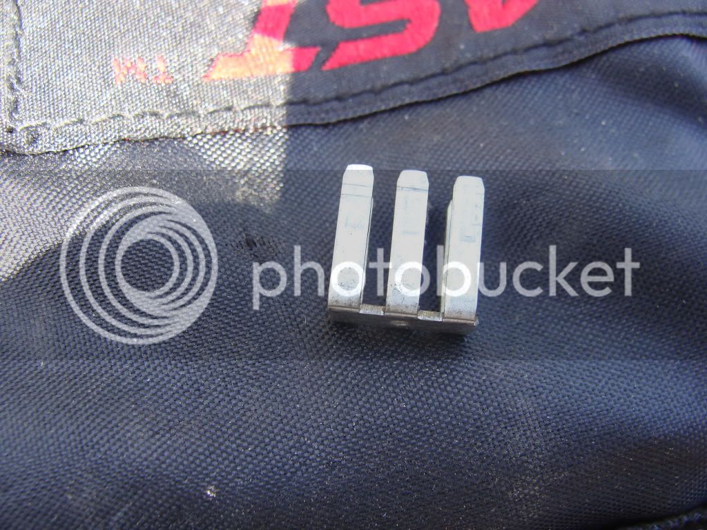
To recap, instead of just dumping the connector and "spider" pin that goes in the connector, then soldering all the wires together, as Smitty did, I thought a better solution might be to dump the connector and "spider" pin, but instead of soldering the wires together, put a ring terminal on the end of each wire going to the connector and screwing them down to a barrier strip.....
.....THEN run a ground from that barrier strip to a grounding point on the engine block.
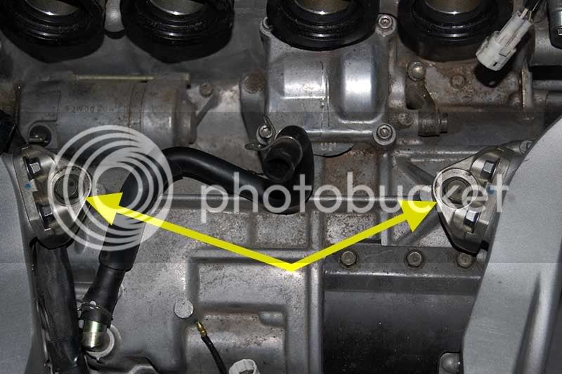
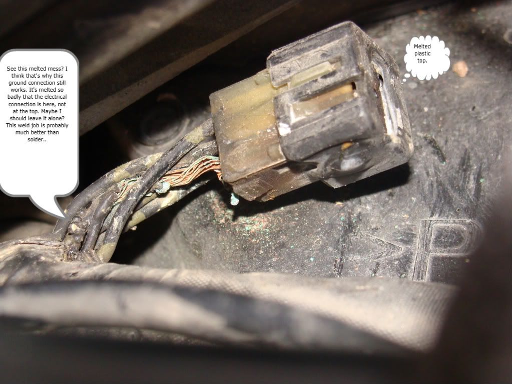
To me, it sounds like the problem is corrosion in the "spider" is creating a resistance heat buildup as current from several circuits looking for ground meet up in that connector. If there was a shorter, and less resitant path to ground from the connector itself, it would make sense some of the heat buildup in the harness would go away as the current is being grounded sooner. Plus, one could use a larger gauge wire to ground than the wires meeting at the connector to provide and even better ground.
Of course this all depends on if the "spider" actually is simply a point to tie 4 or 5 ground wires into one. That is a poor design and could be improved by sending the multiple ground points TO ground sooner.
The resident electrical specialists are more than welcome to chime and and say if my idea has no merit, but to me, it looks like a shortcut was made in the design of the wiring harness to facilitate ease of manufacture and installation and might be helped or even fixed by creating and providing better ground paths at each of the multi-ground connectors.
It also seems that if there are 6 wires going to those connectors, 5 of the wires are grounds for various circuits that are being combined at the junction and then being sent to ground through the 6th wire. Soldering all 6 together doesn't decrease the amperage load on the actual 6th wire one bit. It simply bypasses the connector. It just makes sense to get the current back to ground sooner and through a heavier gauge wire, hence my barrier strip idea.
Make any sense?