hppants
Well-known member
Helped MikeP1300 check his valves this morning. All were in spec, but a few were close to tight spec (both intake and exhaust). We decided to shim them to the loose side of spec all around, hoping to follow Fred's lead and not have to worry about it for a while.
Mistake #1 - we did NOT put the crank on TDC before starting.
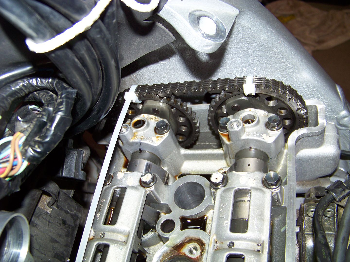
We ziptied both cams to the chain, and ziptied the rotor sensor wheel to the chain as well. Loosened the cam chain and started with the intake. moved the cam over - pulled shims, put back together - all good. One of the intakes (I believe it was #2) had the lobes down. So we had to work against the valves to put the cam on, but it went without trouble.
Pulled the exhaust and the same thing happened.
Mistake #2 - upon trying to reinstall the exhaust cam, lobes on #4 are down, so we rotated the crank slightly to get it to fall in place. Tightened everything down and released the CCT. Untied the zips all around. Now I can't turn the crank a full turn using a rachet on the bolt without hitting something hard.
Oh shit - big mistake #3.
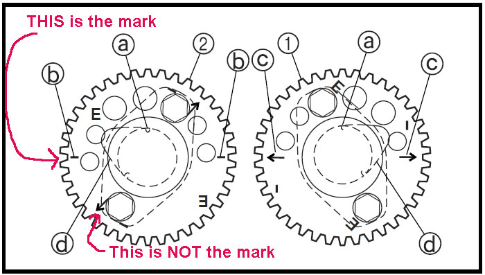
Long story short, we spent the entire afternoon trying to line up the cams and the crank in time. We followed the book except for one thing. The arrows on the cam gears are on the outer side. With the motor in the frame, we can't put our eyes on the arrows. So we pulled the cams and transferred a pencil mark on the inside of the cam gear.
Funny thing about this. On the exhaust side, when the marks are lined up with the cylinder head, the #4 outer cam lobe has the hole at straight up. However, on the intake side, we cannot rotate the camshaft such that the marks are lined up AND the hole is straight up. There are two possibilities for where the cam can be placed. One way, or 180 degress the opposite. On one way, the right most cam lobe is straight up. At 180 degrees opposite, the hole is at about 45 degrees from straight up.
So I put the crank on TDC (with the cams out) and removed the rotor sensor. I then slid the cam chain off the crank gear. We lined up both cams and put the chain on it as tight as we could get between the cam gears. I then moved the chain forward and backward a tooth such that the crank remained on TDC, and both cams lined up with their marks. We then tighten down the camshafts while I held the cam chain in place on the crank gear. After everything is tightened down, the crank has moved about 10 degrees (missed a tooth or two). Again, I can't turn the crank more than about 150 degrees in either direction before I hit a stop.
We tried to repeat with no luck. So on Monday, the bike is going to the dealer.
So.... my biggest questions are:
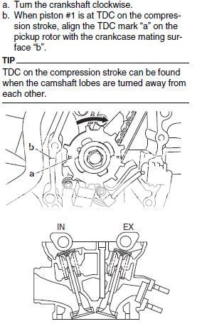
1. When the crank is at TDC, and the cams are lined up correctly (arrows on the head), do the lobe holes on both the exhaust and intake run straight up and down?
2. When the crank is at TDS, and the cams are lined up correctly, are all of the lobes (intake and exhaust) away from the bottom - that is, are ALL 16 valves supposed to be fully closed at that time?
3. If I pushed one (or more) valves against the top of a piston while trying to set the timing, could I have bent the valve using only the force of 2 or 4 of the cam bearing cap bolts? Or more likely did the valve just push the piston down and rotate the crank (which is probably why my TDC mark didn't line up)?
At this point, it's time to pour money on it.
I feel horrible for Mike. I tried to help him and of course I made matters worse.
I think I'm just about done turning wrenches on motorcycles.
Mistake #1 - we did NOT put the crank on TDC before starting.
We ziptied both cams to the chain, and ziptied the rotor sensor wheel to the chain as well. Loosened the cam chain and started with the intake. moved the cam over - pulled shims, put back together - all good. One of the intakes (I believe it was #2) had the lobes down. So we had to work against the valves to put the cam on, but it went without trouble.
Pulled the exhaust and the same thing happened.
Mistake #2 - upon trying to reinstall the exhaust cam, lobes on #4 are down, so we rotated the crank slightly to get it to fall in place. Tightened everything down and released the CCT. Untied the zips all around. Now I can't turn the crank a full turn using a rachet on the bolt without hitting something hard.
Oh shit - big mistake #3.
Long story short, we spent the entire afternoon trying to line up the cams and the crank in time. We followed the book except for one thing. The arrows on the cam gears are on the outer side. With the motor in the frame, we can't put our eyes on the arrows. So we pulled the cams and transferred a pencil mark on the inside of the cam gear.
Funny thing about this. On the exhaust side, when the marks are lined up with the cylinder head, the #4 outer cam lobe has the hole at straight up. However, on the intake side, we cannot rotate the camshaft such that the marks are lined up AND the hole is straight up. There are two possibilities for where the cam can be placed. One way, or 180 degress the opposite. On one way, the right most cam lobe is straight up. At 180 degrees opposite, the hole is at about 45 degrees from straight up.
So I put the crank on TDC (with the cams out) and removed the rotor sensor. I then slid the cam chain off the crank gear. We lined up both cams and put the chain on it as tight as we could get between the cam gears. I then moved the chain forward and backward a tooth such that the crank remained on TDC, and both cams lined up with their marks. We then tighten down the camshafts while I held the cam chain in place on the crank gear. After everything is tightened down, the crank has moved about 10 degrees (missed a tooth or two). Again, I can't turn the crank more than about 150 degrees in either direction before I hit a stop.
We tried to repeat with no luck. So on Monday, the bike is going to the dealer.
So.... my biggest questions are:
1. When the crank is at TDC, and the cams are lined up correctly (arrows on the head), do the lobe holes on both the exhaust and intake run straight up and down?
2. When the crank is at TDS, and the cams are lined up correctly, are all of the lobes (intake and exhaust) away from the bottom - that is, are ALL 16 valves supposed to be fully closed at that time?
3. If I pushed one (or more) valves against the top of a piston while trying to set the timing, could I have bent the valve using only the force of 2 or 4 of the cam bearing cap bolts? Or more likely did the valve just push the piston down and rotate the crank (which is probably why my TDC mark didn't line up)?
At this point, it's time to pour money on it.
I feel horrible for Mike. I tried to help him and of course I made matters worse.
I think I'm just about done turning wrenches on motorcycles.
Last edited by a moderator: