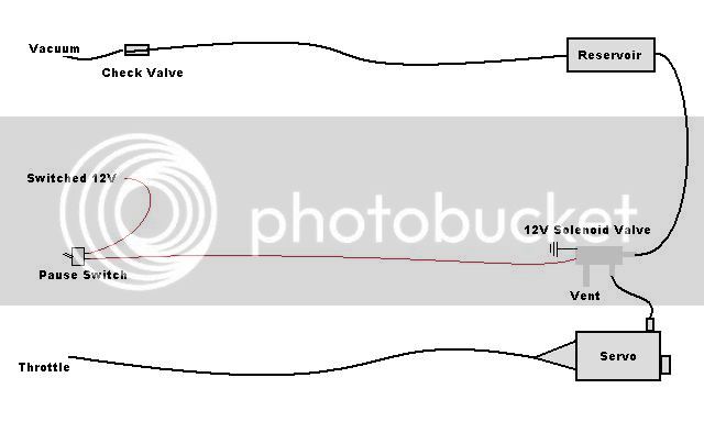
Shazam!! Venting of the servo unit is a big find, and in retrospect makes all the sense in the world (which is probably why nobody thought of it before? :huh: ) .
...
Does make sense, doesn't it?
...
In the past we've all been concerned with ensuring we have adequate vacuum / suction for pulling in the throttle, but never paid much attention to the ability to release it. My CC is under the seat (taking up > 1/2 of the tool tray) so I did not bother going to the extremes of waterproof sealing that you rear wheel mount guys have to. I wonder if there would be any advantage to venting a non-silicone-sealed unit?
The air must be entering the stock servo body via the cable cover, which is somewhat sealed with a strip of foam rubber. In my case, as in yours, I have my servo oriented such that the wires and foam seal are on the top. Any casual water sitting on that seal might get sucked into the servo. Maybe a new winter project for me this year.
")
...
When I first looked at the cover, my immediate thought was that it was waterproof always provided that the wires lay nicely in the grooves. The cover seemed a close fit all round except where the wires pass through, and the rubber seal looked well implemented. So, if air can be sucked through the rubber seal, it won't be very quickly, but maybe fast enough. (At that stage I'd given no thought to air getting in, that requirement never occurred to me.)
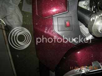
These two pics show the seal (the one of the lid has my extra sealant, you can just see the foam rubber under that - it's the only picture I have that shows the detail)
(Click on image for larger view)

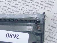
As for whether you need to seal yours, I would say probably not, provided the wires are laying correctly, there shouldn't be much water in the tool tray area (I've never known any). I only decided to seal mine because I could envisage water coming hard off the tyre which could force its way through the seal.
Having said that, if it is really water tight, you probably need a vent. I'm almost wondering whether Audiovox hadn't considered this when they designed the thing.
...Also, FWIW, I am that other forum member that ionbeam mentioned earlier who found some issues with using multiple vacuum ports, even with check valves. Being an obsessive
RDCUaTBS guy, I know exactly how my engine feels when everything is in good balance. On my bike there is a turbine like smoothness that happens between ~3k and 4500 rpm when everything is perfect and I enjoy running in that range greatly.
I'd built up a four way manifold of vacuum tubing and tee connectors with check valves at each of the four vacuum port take-offs but immediately noticed that the TBS felt off. When I removed the manifold and went back to a single vacuum port and it was smooth again. I checked each of the check valves and they were all operating correctly. I cannot explain how or why it happened. Since these tubes must all be removed to measure the vacuum balance I couldn't investigate it any further without adding additional tees in the manifold to be used as service ports. Rather than doing that I decided to just stick with a single vacuum port which seems to work fine anyway.
I'm only using one TBS port, testing so far suggests it's adequate (but I've not done many miles yet). The only reason I could see multiple ports causing an engine running problem is if you got any check valves the wrong way round, but I expect you've made sure they are correct. I also seem to remember reading somewhere that teeing off the intake air pressure sensor port(s) is bad (don't ask me why).
[edit]Found a reference about not using the inlet pressure sense ports
here, but it seems to be contentious [/edit]
I've noticed no difference in engine smoothness after fitting the CC. I've not done a TBS of any sort, let alone the
RDCUaTBS one. And my '10 is definitely smoother than my '06; I'd TBS'd that, but not in an unauthorised way.
As for the "Cancelling" suggestions:
I didn't really want to add another switch,
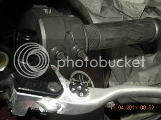
Tapping either brake seems to need sufficient movement to actually apply the brake,
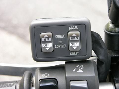
Rocking the OFF-ON switch requires a bit of my attention because I haven't learned their position without looking, and, of course, my attention needs to be on whatever is causing me to want to slow down. But the latter is the simplest in terms of "extras".
Ok, I'm just fussy
.