Gen 1 cruise control question

Yamaha FJR Motorcycle Forum

Help Support Yamaha FJR Motorcycle Forum:

This site may earn a commission from merchant affiliate links, including eBay, Amazon, and others.

Chiefblueman

Well-known member
Joined
Aug 1, 2012
Messages
370
Reaction score
121
Location
Duvall,WA
I'm about to pull the trigger on the Audiovox CCS100 from Murph's. Due to a lot of searching this great forum, I've learned a great deal about installation. Most of the info Ive found pertains to Gen 2 which is OK except for one thing - servo location. Brundog, Smitty and FJRcarshopguy had great threads but I'm looking for locations for the servo besides the tool tray. Can't go under the right sidecover, ABS resides there. Any suggestions? TIA

Humbly,

C-Bman

 
The easiest place to put the servo is at the tool tray. It will fit other places with a bit more work and creativity.

This is where I put my servo 100K miles ago and it has remained 100% reliable in this location.

bags_sm.jpg


nobags_sm.jpg


vac_sm.jpg


If you don't like the appearance you can paint it light blue and put a NOS sticker on it
wink.png


The MC Cruise kit for an ABS FJR puts the servo between the pillion's foot peg and the driver's foot peg. In this location it would interfere with Good Pillion's dropped pegs and foot location. In the linked brochure scroll down for a picture of the MC location.

Stretching it some more, the servo can be made to fit behind the front chin fairing and the headers. I dunno why, but it has taken the heat and been a reliable install.

cruise001.jpg


cruise002.jpg


With A LOT more work, you can drop the rear suspension and cram the servo in between the back of the engine and the shock.

sideview.jpg


gothroughhere.jpg


I don't know for sure on a Gen I, but I know for sure on the Gen II the servo will fit up front at the chin fairing where the CA smog canister mounts. The two holes are where the CA smog canister bolts.

SMOGCANBRACKET.jpg


Again for A LOT of work the servo can be taken apart. I don't know about a Gen I, but I know for sure on a Gen II the servo can have the back third separated allowing the servo to be put under the tank, between the steering stem and the engine, then snapped back together.

So, that's a few options beyond the tool tray. Is the tool tray looking like a better choice now? :lol:

 
Last edited by a moderator:
Ionbeam, you're an amazing source of all things FJR and then some. You rock, dude
punk.gif


The tool tray looks great except for the PCIII and FZ1 fuse block inhabiting that space. Relocation may be in the cards. You did show me a couple spots I hadn't thought of and I will be considering each of them. The spot between engine and shock actually looks quite doable, theres an unused tab on the engine there. I have also been considering a spot ahead of the shock where the preload adjuster used to reside.

Thanks for the response!

 
Mine sits on top of the valve cover, behind the steering stem.

Check your valves during the install since it requires removing

the coolant pipe anyway.

 
Thanks, guys. I had seen the thread by Useless Pickles. Unfortunately, Gen 1 and Gen 2 aren't the same in the aft of steering stem area. That area on the Gen 1 is stuffed with the main wiring harnesses and a thermostat housing. If I had a Gen 2 l'd definitely think about stuffing it in there but there's no way I'm gonna try to relocate the wiring in this area.

Good news is relocating the PCIII is going to be easy, leaving room for the servo in the tool tray next to the FZ1 (I hope). Does anybody know the dimensions of the servo? I'm using a can of cranberry sauce for mock up, 3" diameter X 4" long. With this arrangement I'll still be able to carry a pretty comprehensive tool kit and small spares under the seat. Not so sure about the Slime air pump.

Thanks for your responses. Youse guyz r a great buncha fellas
clapping.gif


Seriously another cruise control question! Y'all are ganging up on me. I have noodled this thing to death. This installation scares the heck out of me, and I haven't even bought a cruise yet. It is one of those things that I would really like on the bike. I have a throttle meister but a full blown cruise would be flipping fantastic.

 
<blockquote class='ipsBlockquote'data-author="graler" data-cid="1121565" data-time="1390800266"><p>

Seriously another cruise control question! Y'all are ganging up on me. I have noodled this thing to death. This installation scares the heck out of me, and I haven't even bought a cruise yet. It is one of those things that I would really like on the bike. I have a throttle meister but a full blown cruise would be flipping fantastic.</p></blockquote>

A DIY installation like this requires, above all else, patience.

An understanding that worthwhile results take time.

See this project as perhaps taking several days ( because of

interruptions ) and not a few hours.

And, when presented with a problem, to seek solutions and

not get frustrated.

Break the install down into several small steps instead of one

big project and tackle them one at a time: cable attachment,

servo location, control pad, wiring, vacuum hoses, etc.

Obtain and use the proper tools and hardware for each step.

Be neat, concise and don't take shortcuts.

Don't be afraid to ask for help from those who've done this before.

Good luck.

 
The following is not intended to be an install guide, it is just an overview of project management.

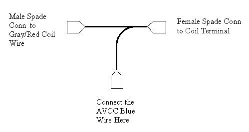
On a big project like the Cruise Control, break the install into sections. I set up a 6' long folding table and lay out all the parts as they will be installed on the bike so I get an idea of how it will need to be routed and mounted. I will also use this to help layout any wiring, fuses, connectors and switches that I may need to add to the install. This helps me understand what connectors and wiring bits I will need to buy or fabricate. The following drawing is a little "Y" using spade connectors that I made in advance to attach the CC harness to the coil without cutting or splicing wires (get the connector's sex correct!):

CoilTee.jpg


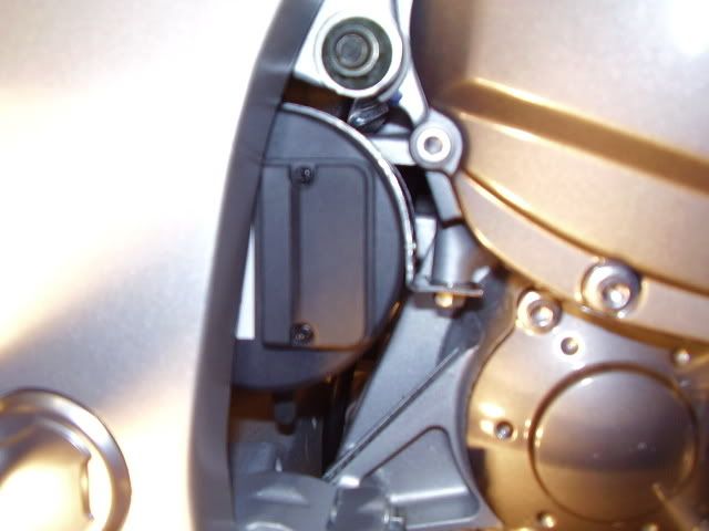
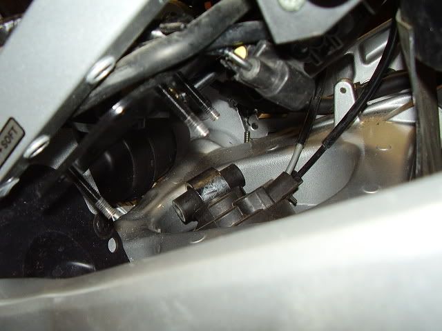
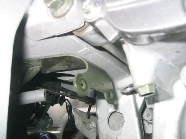
Start with the key items. First drill the throttle tab, this must be successfully done or there is no point in going on. Now attach the bead chain to the tab and get the hardware positioned with clearance then tie a string to the bead chain and tie the other end to something so you can pull up the chain once ready to connect it to the servo cable. This gets one of the more aggravating things out of the way early. Now you can see where other things go, like brackets. Bend, fold, drill and twist any metal that will be used and paint it so you won't have to interrupt the assembly. The metal strap that holds my CC on the swing arm was prefabricated and painted. Seal up the control pad and sort out the mounting for the control pad so it is ready to go.

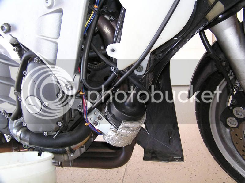
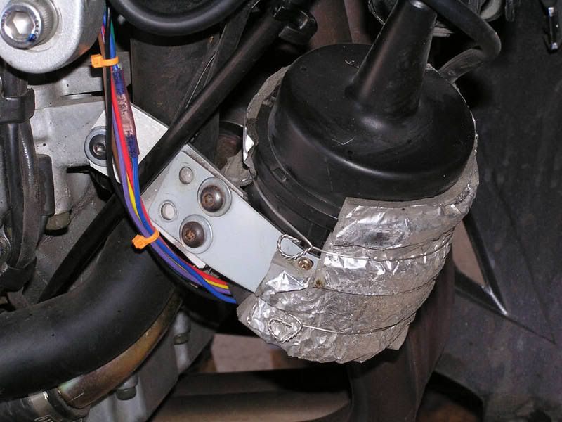
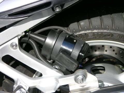
Look at all the harness wires, loose wires and the servo cable and figure out where they need to run and what holes and openings they will snake through on the frame and around the engine. Now you will be able to see what you need to take off the bike to route the wires and vacuum line. Look at your wire routing and see if the wires need some form of loom or armor, install as much as you can on the bench before installing on the bike. Note the corrugated armor I used on my servo wires because it runs past hot and moving items.

vac_sm.jpg


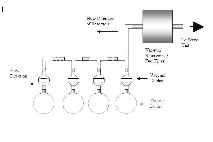
Plan out how you are going to manage the vacuum at the intake manifold. This will help you put together a shopping list and prefabricate parts. The generic drawing I made will let you see how many connectors and Tees you may need as well as the vacuum diodes (check valves) and reservoir. I chose to tap all four throttle bodies, others have tapped fewer. Pay attention to the check valves flow direction! This setup has 3 Tees and 1 90º elbow. I see I forgot to shade the rubber hose that runs to the reservoir. Oops! I used a '85 Gold Wing gas filter as my reservoir.

AVCCThrottleBodyConnections.jpg


This isn't a race, leave time to get it done. The control pad will take time to dry after sealing, paint will take time to dry. One of the hardest things I have learned about doing this kind of project is when to take a break or walk away and come back later with a better attitude or rested body. Once you are tired or frustrated things start to go wrong and it only gets worse from there if you continue. This is why I usually tell people that a CC install isn't a good tech DAY project. If you install a lot of these kits like Smitty did they can be done in ~4 hrs but if you are doing it for the first time leave your self time to do the work and break time to walk away.

Good luck!

 
Last edited by a moderator:
When I added mine (GEN1), I found the following link very helpful:...
Yes, the procedure shows a NON-ABS FJR. I used that procedure from H. Marc Lewis web site as a guide when I installed my CC, there are also a few other very good guides here on the Forum; more procedures -- 1 2 3a 3b 4 There are a few things from the FJR1300.info procedure I would like to single out.

When setting the DIP switches in the servo, switch #7 should be switched OFF, especially if you have a Gen II. You want the switch OFF to tell the servo that the signal is an ECM signal (in car speak, FJR speak is ECU) and not a coil signal(1). If this switch is set to ON in a Gen II there will be odd problems show up that will prevent the CC from working or cause abrupt shut off for no apparent reason which is difficult to troubleshoot so always set #7 to OFF.

The Purple brake wire must go as close to 0.00 volts as possible when the brake is off. Even a small voltage like 0.300 can be enough to prevent the cruise from setting. This is especially a problem on a Gen II and often requires a relay to be added to prevent the voltage offset.

The unmentioned Gray wire from the control pad is the back-light power for the buttons. It should be connected to switched 12 volts.

And a reminder, the cruise will not set with your bike on the center stand, it will only set when moving on the road
smile.png


(1) On olde school vehicles with a breaker point ignition system switch 7 should be ON/COIL, on modern vehicles with computer controlled ignition it should be set to ECM/ECU.

 
Last edited by a moderator:
Top