Gen I Rostra Install Advice Needed

Yamaha FJR Motorcycle Forum

Help Support Yamaha FJR Motorcycle Forum:

This site may earn a commission from merchant affiliate links, including eBay, Amazon, and others.
The hardware I added to get this thing working was:
Rostra Switch 250-3592 + relay for engaged indicator light

Rostra vss kit 250-4165

Koso M6x20mm Speed Sensor Magnet Bolts BF010611

Black Vinyl Sleeving to dress up the vss wires as they route up the swing arm
Could you post a pic of how you used the magnet bolts & sensor on the wheel? I'm not clear on how you did this.

Thanks -

 
IMG_1603_zps5ltxnhnp.png


Thanks, I see now!

And the sensor is on the swingarm? How close does it need to be to the magnets??

I am running a CCS 100 now and it's been problematic throughout the time it's been on there (~100K+ miles). I have a Rostra on the shelf I was saving for something else, but that project has gone away. After this last trip to Red Lodge I'm just about fed up with the old setup so was interested in how you did yours. Thanks for the info.

Edit: I couldn't see the sensor at first, but now do below the abs sensor. It looks like you used some aluminum angle (or bent up some to an angle) and attached it to the swingarm - drilled and tapped the top of the swingarm?

 
Last edited by a moderator:
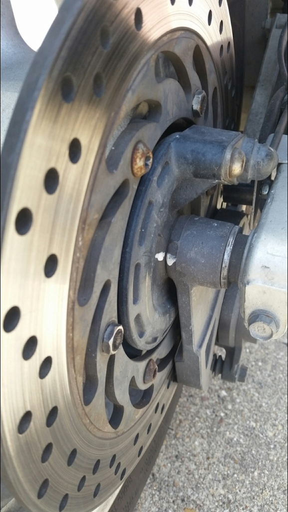
I put mine on the swing arm just in front of the abs sensor. Looking past the bottom of the abs sensor in the pic, a black object can be seen in the background, that's the vss pickup coil. The manual said .5 to 1 inch away from the magnets which didn't work for me. I ended up putting it about .125 to .25 inch off of the magnets with about a .375 inch or so offset off of center. Let me know if you need better pics of it, my son owns the bike now, but we are visiting him this weekend.

"Edit: I couldn't see the sensor at first, but now do below the abs sensor. It looks like you used some aluminum angle (or bent up some to an angle) and attached it to the swingarm - drilled and tapped the top of the swingarm? "

Yes, the kit came with some generic bracket material, I trimmed a piece of angle out of that and painted it silver to match the swingarm, and mounted it to the swing arm. It seems to blend in fairly well, I think it would take a fjr owner to be able to spot it.

 
Last edited by a moderator:
Many thanks NTXFJR. I just completed the installation of a Rostra cc on my 2005 FJR and it behave exactly like yours before you managed to find the fix. Looks like I found the solution through your posts.

Questions :

1- Where did you find those Koso bolts?

2- How does the Rostra vss kit connects to the circuit? (I suppose there is a schematic with the kit?...)

 
I just completed my second Rostra CC installation on my friend 2012 FJR, (mine being a 2005 no abs). It is working pretty well but the speed has a tendancy to fluctuate a bit when going downhill (Is that what you call surging?) and also have a tendancy to disengage itself for no apparent reason.

As the control switch is the one with the engaged led light (with about 2 dozen wires coming out of it...), I decided to join together 2 wires (the blue and the white) that needed switched power and connected them on the brown wire that powers the actuator trough the 10 amp fuse. My question is : Is that possible that this set up is putting to much load on the brown wire and causes an occasional voltage drop, and causing the CC to disengage?

 
I finally cured the disengage problem by disconnecting and grounding the blue tach wire...[as per the manual]... and yes, mine does surge somewhat when going downhill....haven't fixed that yet and prolly won't as it is not that bad....I usually just hold pressure against the throttle until off the hill..

 
I found my ‘’disengage’’ problem while I wanted to reroute some wires from the control pad lighting that I had initially connected to the brown main wire, to connect them to a different circuit. When I touched the brown wire end connector, it just fell between my fingers. It was broken! I soldered it back to the brown wire, reconnected it in the fuse box and went for an half hour ride, playing with different speed settings, between 80 and 110 km/h and the cc was holding the set speed well and never disengaged again.

My next Rostra cc installation was on a 2016 FJ 09. The only installation instructions I have found are from BuilderBob in the FJ 09 forum. It is engaging smoothly but does not hold the set speed, going abruptly up and down 4-5 km/h. Sometimes it will stabilise going uphill though. Do you have any idea what is the PPM on a 2016 FJ09 or where I can find this information?

My next move will be to try to increase the leverage at the throttle control cable connexion to make it less sensitive.

The DIP switch setting is as follow : 1-2 OFF 3-4-5-6 ON 7-8-9 OFF 10 ON 11-12 OFF

Thank you in advance for your help.

 
After reading tremendous amount of informations on Rostra cc installation on Kawasaki Concours C14, I found a solution to the surging problem I was encountering on my FJ09 installation. So I am posting this because I think it may apply to all motorcycles because of the fact that the power to weight ratio on a motorcycle is very high and may exceed the capability of the Rostra cc even at its lowest DIP settings. On the C14, the throttle arm where they hook up the cc control cable is much longer (and VERY easy to access by the way...) and they manage to have a very smooth response of the Rostra.

On the FJ09 the throttle pulley is very small and the point of attachment to the throttle stop makes a very short lever to the cc cable to pull. So I manage to make a bracket that attaches to the center pivot of the throttle pulley like some guys did on their FJR installation. This multiplied the leverage by almost 3 and made the cc work very smoothly.

 
Top