


ARFJR
Well-known member
Another new way to mount the Audiovox CCS100 on the AE.
Trying to think outside of the box I came up with mounting the Audiovox CCS100 servo in the tail of the bike.
This area seemed better IMHO than the other locations used as:
1. The area is designed to hold something. (Note the supplied tie-down straps.)
2. I had no other plans for the space.
3. The servo would not be subjected to heat from the headers, the wet/dirty environ behind the bags, or the possibility of nixing the warranty by moving all the computer modules away from their tool tray support.
The only minor problem was the needed ½” of clearance in the tail between the pillion seat and the aluminum vertical frame supports just in front of the electrical sockets for the tail lights.
The only major problem seemed to be in the length of the servo cable. The increased distance from the throttle would not allow the cable to be mounted in the typical way.
The minor problem:
A difficulty in placing the servo in the tail was estimating the amount of material that would need to be removed for clearance. Taking a Dremel tool with a conical carbide grinding bit to my new motorcycle wasn’t easy either.
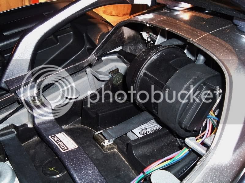
There are four vertical supports (1/8”x1.25”x5”) in this area. The three toward the left side of the bike (the three on the right if you are facing your work) are the ones that need trimming. After removing ½”to 5/8” in a semi-circular pattern from these three supports, the servo had a new home. The pillion seat will now hold the servo in place.
Facing the tail of your bike, note that the servo will sit toward the right side of the area. This allows an extra inch or so for cable clearance to the left. The bend in the cable is a bit more than the 4” max radius the manufacturer recommends in the installation instructions, but I can’t tell that there is any binding or resistance at all.
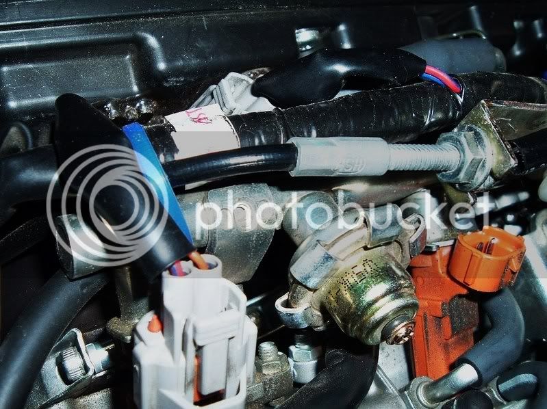
Route the cable under the pillion seat hold-down tabs and then foreward along the right side. The cable end should end at just about the perfect length from the right side of the fuel rail.
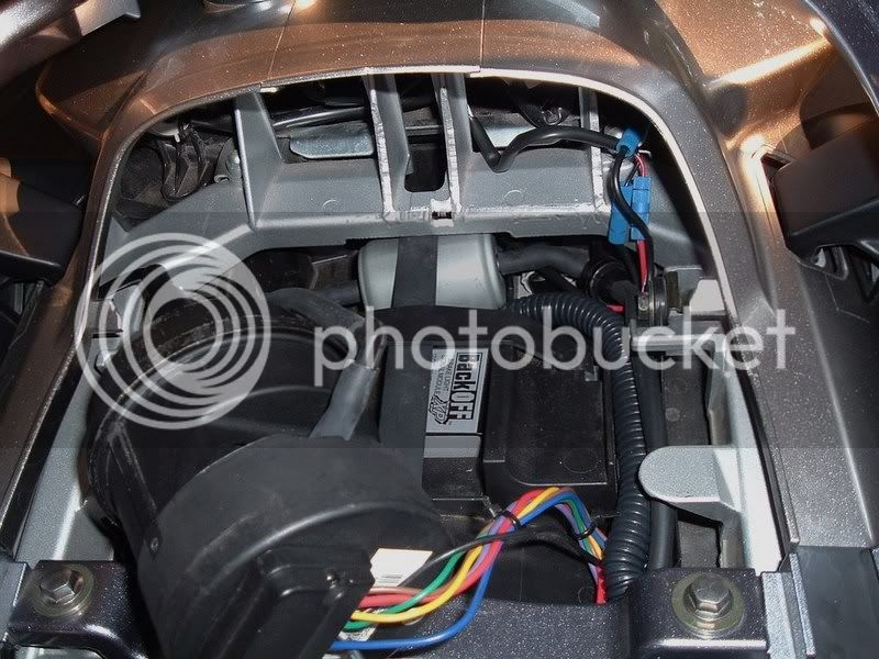
The wiring from the servo runs along the left side of the bike. We’ll get to that in a bit.
The major problem:
Instead of following the throttle cable and using it to anchor the servo cable, I elected to route the cable along the fuel rail from the right side of the bike.
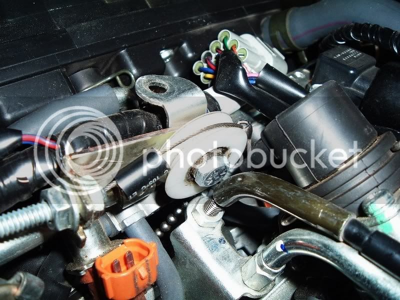
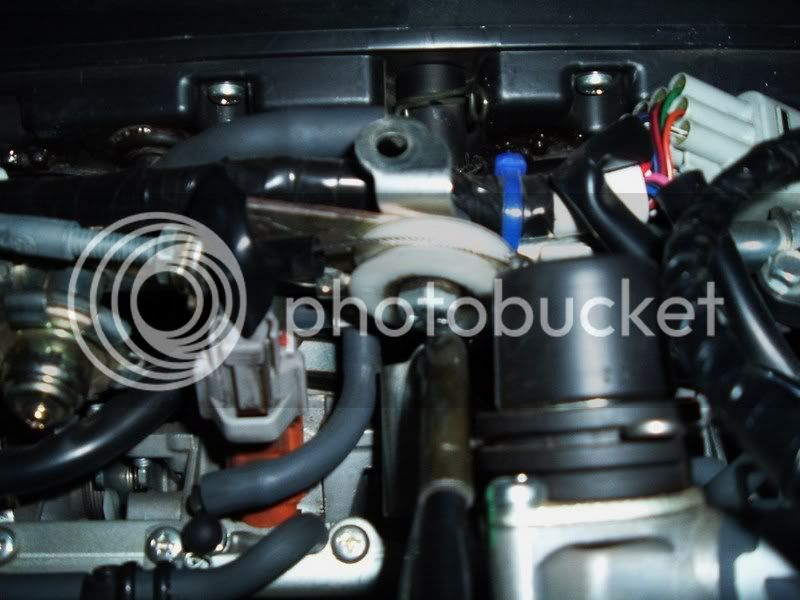
The 06/07 FJR has a bracket that is used to hold down the heat shield. This is almost too convenient for the secondary purpose of mounting a nylon pivot wheel and the smaller piece of the cable mounting bracket from the CCS kit (Part #16) which would allow the bead chain from the CCS kit to make a 90 degree turn, be supported appropriately, and be centered over the throttle stop tab.
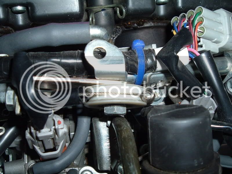
The “pivot” wheel (1-1/4”diameter) I found at Home Depot. It is a replacement support “runner” for sliding glass doors. It comes in a package of 2 for a few bucks.
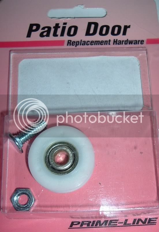
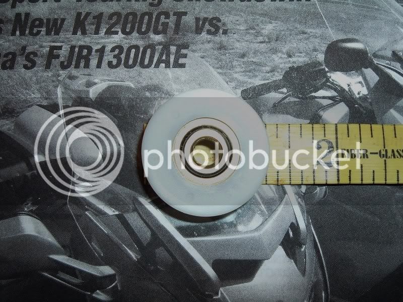
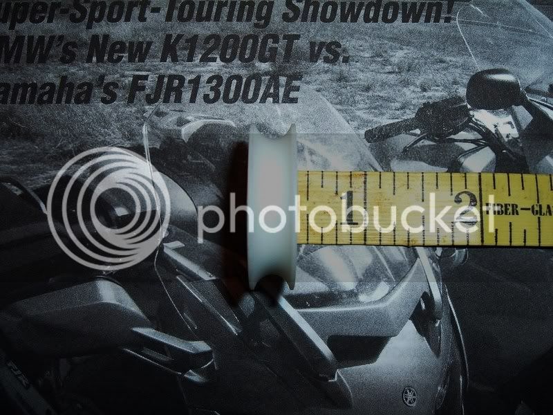
It has steel roller bearings and a 3/16”” tracking groove on its’ edge which is the perfect size for the bead chain. The service life should be more than adequate considering the weight this wheel was designed to support. These wheels come with mounting bolts that are too short to use for this purpose. Get a ¾”length bolt while you’re at the store.
Mount the bead chain to the throttle stop tab in the traditional way.
https://www.fjr1300.info/howto/audiovox.html
Note: Removal of the fuel rail, the injector wire harness, and the air injection valve and its hoses, is the only way to go with this step. This is not a big deal. Just be careful not to loose the 2 aluminum spacer/supports for the fuel rail.
Replace all the above after you’ve mounted the bead chain to the stop tab.
Don’t drop the loose end of the chain! It can be a bitch to fish out if you do. I used a hemostat to hold it until it was attached to the servo cable. You’ll end up using a 7-bead or so length of chain.
This would be as good a time as any to attach the CCS mounting bracket (Part#16). Use only the short section of the “assembly”. There are two ways to attach this part to the cable. You’ll have to fit it to where the part follows the length of the cable. The tab on the end of the part fits between the two adjusting nuts on the cable end. The opposite end of the part has the hole that will attach to the heat shield bracket along with the nylon wheel. The other tab on the bracket I ground off, as it seemed to make the cable adjustments a bit too tight for wrenching.
Drill a ¼” diameter hole 1.5” from top of heat shield bracket. (You want to position the top of the pivot wheel slightly below the top of the bracket to clear the heat shield.)
Use a ¾” length bolt (not in kit), with a flat washer spacer, and a star type lock washer, and the mounting bracket (Part #16) from the kit and a bit of blue lock tight. (If you haven’t already) Snug the servo cable in the bracket from the kit using the adjusting nuts on the end of the cable. Mount it with bolt, spacer washer (between the bracket and wheel), star washer, and nut (through the new hole in the heat shield bracket).
Note: The flat washer is to help center the nylon wheel over the throttle stop tab.
Wrap the bead chain around the wheel (no slack, but not too tight).
With the servo cable fully extended from its’ sheath, trim off the extra beads in the chain that you don’t need, then attach the bead chain to the end of the servo cable using the bead chain coupling (Part# 24). I also added one of the bead chain coupling sleeves just because. Adjust tension with cable adjusting nuts and bracket (again with no slack, but not too tight). Tighten everything securely and presto!
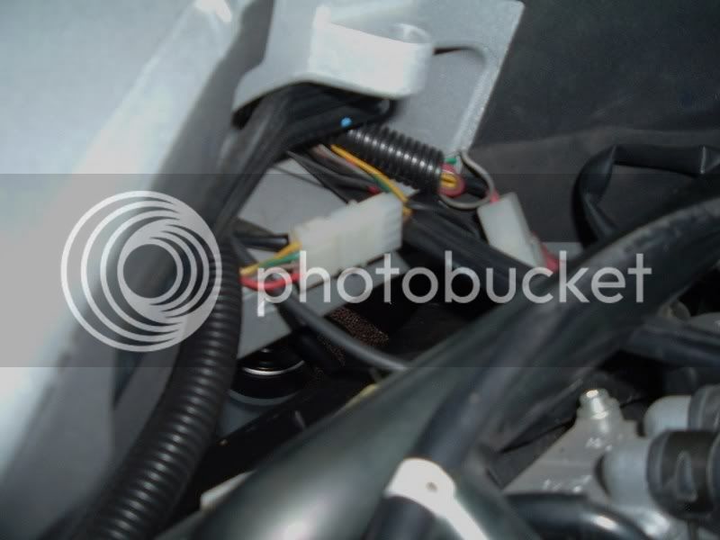
The wires coming from the servo were routed along the left side of the bike. This was appropriate due to the location of the bikes’ tail wiring harness where you’ll need to splice the purple kit wire to the bike yellow (stop light) wire, the red kit wire to the bike blue (tail light) wire, and the black kit wire to the bike black (ground) wire.
Wiring harness access is also along this side where all the computer connectors are. I tapped into the gray with red stripe wire at the top row 2nd from the left pin on the ECM connector for the blue wire from the servo kit for the tach signal. This gray/red wire is the negative wire from the more outboard board ignition coil (You could also choose to use the orange wire next to the gray /red wire).
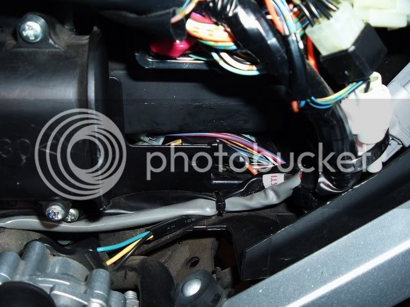
I also tapped into the brown/white wire at the 8pin plug (which is located under the ECM) with the fused orange kit wire for a power source. The brown /white wire is the
switched power supply for the ABS computer.
Then I added about 3’ of red 16ga wire to the other end of the fused orange wire and routed it with the rest of the kit wires (for the control pad) toward the front of the bike.
Note: The blue noise suppression wire should not be trimmed much. I routed it with the other wires toward the front of the bike and then doubled it back to where I tapped into the gray with red stripe wire at the ECM.
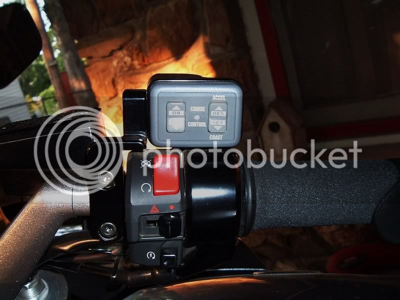
Mount the control pad however you see fit. I used Skyway’s right side mount and ran the wires through a length of black heat shrink tubing. This bundle terminated under the front of the gas tank and under the heat shield where I placed the 4-pin connector.
I chose not to connect the gray wire. It supplies power to the LEDs that illuminate the control pad. It seemed a bit to bright green for my taste and I didn’t think I needed the pad lit anyway.
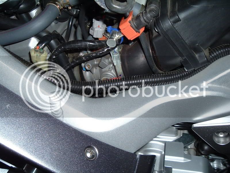
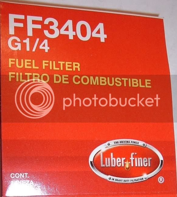
After using the CCS-100 unit for a few months I came to the conclusion that a small vacuum reservoir was necessary. I got the idea of using a small metal gas filter from someone else on the forum who I’d give credit to if I could remember who it was (Thanks).
I went to Autozone and got their generic model # FF3404. The overall size and fittings looked about right (4.5”x 2.5”). I also got a check valve and a foot of the same vacuum tubing as what had come with the CCS kit.
First I connected the kit tubing to the throttle body vacuum fitting for cylinder #1. Then I routed this along the left side of the bike toward the tail. Then I attached the check valve, to the gas filter, and lastly the CCS servo.
All was tucked neatly to the rear behind the servo unit (completely out-of-site).
CCS operation has been noticeably more smooth on hills and at more wide open throttle conditions (steeper hills, resume speed control, ect.).
A special thanks to Skyway for the precision milled aluminum right hand mount for the control pad. https://www.fjrforum.com/forum//index.php?showtopic=4507
I had it powder coated black. It’s the cat’s ass! I do wish I could have mounted the control on the left (AE trigger mount is in the way) but it works just fine on the right.
BTW- All the usual and expected disclaimers apply.
Trying to think outside of the box I came up with mounting the Audiovox CCS100 servo in the tail of the bike.
This area seemed better IMHO than the other locations used as:
1. The area is designed to hold something. (Note the supplied tie-down straps.)
2. I had no other plans for the space.
3. The servo would not be subjected to heat from the headers, the wet/dirty environ behind the bags, or the possibility of nixing the warranty by moving all the computer modules away from their tool tray support.
The only minor problem was the needed ½” of clearance in the tail between the pillion seat and the aluminum vertical frame supports just in front of the electrical sockets for the tail lights.
The only major problem seemed to be in the length of the servo cable. The increased distance from the throttle would not allow the cable to be mounted in the typical way.
The minor problem:
A difficulty in placing the servo in the tail was estimating the amount of material that would need to be removed for clearance. Taking a Dremel tool with a conical carbide grinding bit to my new motorcycle wasn’t easy either.
There are four vertical supports (1/8”x1.25”x5”) in this area. The three toward the left side of the bike (the three on the right if you are facing your work) are the ones that need trimming. After removing ½”to 5/8” in a semi-circular pattern from these three supports, the servo had a new home. The pillion seat will now hold the servo in place.
Facing the tail of your bike, note that the servo will sit toward the right side of the area. This allows an extra inch or so for cable clearance to the left. The bend in the cable is a bit more than the 4” max radius the manufacturer recommends in the installation instructions, but I can’t tell that there is any binding or resistance at all.
Route the cable under the pillion seat hold-down tabs and then foreward along the right side. The cable end should end at just about the perfect length from the right side of the fuel rail.
The wiring from the servo runs along the left side of the bike. We’ll get to that in a bit.
The major problem:
Instead of following the throttle cable and using it to anchor the servo cable, I elected to route the cable along the fuel rail from the right side of the bike.
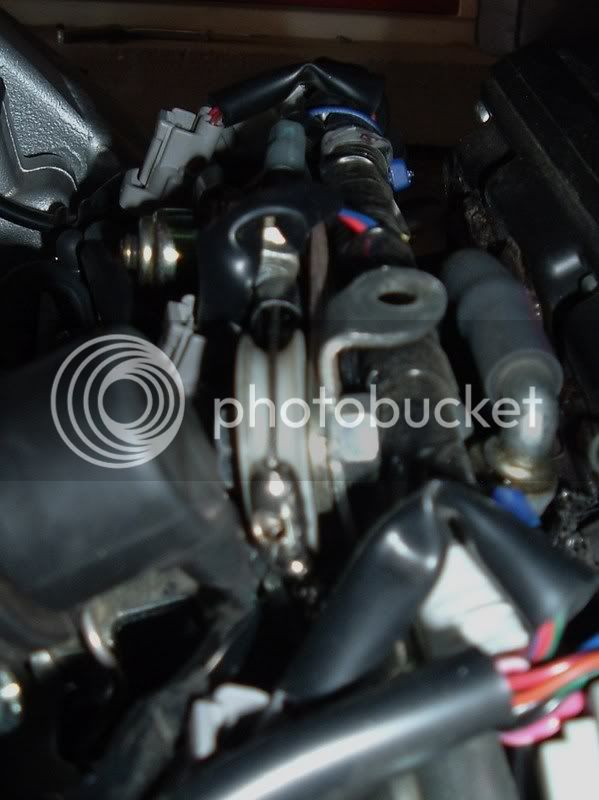
The 06/07 FJR has a bracket that is used to hold down the heat shield. This is almost too convenient for the secondary purpose of mounting a nylon pivot wheel and the smaller piece of the cable mounting bracket from the CCS kit (Part #16) which would allow the bead chain from the CCS kit to make a 90 degree turn, be supported appropriately, and be centered over the throttle stop tab.
The “pivot” wheel (1-1/4”diameter) I found at Home Depot. It is a replacement support “runner” for sliding glass doors. It comes in a package of 2 for a few bucks.
It has steel roller bearings and a 3/16”” tracking groove on its’ edge which is the perfect size for the bead chain. The service life should be more than adequate considering the weight this wheel was designed to support. These wheels come with mounting bolts that are too short to use for this purpose. Get a ¾”length bolt while you’re at the store.
Mount the bead chain to the throttle stop tab in the traditional way.
https://www.fjr1300.info/howto/audiovox.html
Note: Removal of the fuel rail, the injector wire harness, and the air injection valve and its hoses, is the only way to go with this step. This is not a big deal. Just be careful not to loose the 2 aluminum spacer/supports for the fuel rail.
Replace all the above after you’ve mounted the bead chain to the stop tab.
Don’t drop the loose end of the chain! It can be a bitch to fish out if you do. I used a hemostat to hold it until it was attached to the servo cable. You’ll end up using a 7-bead or so length of chain.
This would be as good a time as any to attach the CCS mounting bracket (Part#16). Use only the short section of the “assembly”. There are two ways to attach this part to the cable. You’ll have to fit it to where the part follows the length of the cable. The tab on the end of the part fits between the two adjusting nuts on the cable end. The opposite end of the part has the hole that will attach to the heat shield bracket along with the nylon wheel. The other tab on the bracket I ground off, as it seemed to make the cable adjustments a bit too tight for wrenching.
Drill a ¼” diameter hole 1.5” from top of heat shield bracket. (You want to position the top of the pivot wheel slightly below the top of the bracket to clear the heat shield.)
Use a ¾” length bolt (not in kit), with a flat washer spacer, and a star type lock washer, and the mounting bracket (Part #16) from the kit and a bit of blue lock tight. (If you haven’t already) Snug the servo cable in the bracket from the kit using the adjusting nuts on the end of the cable. Mount it with bolt, spacer washer (between the bracket and wheel), star washer, and nut (through the new hole in the heat shield bracket).
Note: The flat washer is to help center the nylon wheel over the throttle stop tab.
Wrap the bead chain around the wheel (no slack, but not too tight).
With the servo cable fully extended from its’ sheath, trim off the extra beads in the chain that you don’t need, then attach the bead chain to the end of the servo cable using the bead chain coupling (Part# 24). I also added one of the bead chain coupling sleeves just because. Adjust tension with cable adjusting nuts and bracket (again with no slack, but not too tight). Tighten everything securely and presto!
The wires coming from the servo were routed along the left side of the bike. This was appropriate due to the location of the bikes’ tail wiring harness where you’ll need to splice the purple kit wire to the bike yellow (stop light) wire, the red kit wire to the bike blue (tail light) wire, and the black kit wire to the bike black (ground) wire.
Wiring harness access is also along this side where all the computer connectors are. I tapped into the gray with red stripe wire at the top row 2nd from the left pin on the ECM connector for the blue wire from the servo kit for the tach signal. This gray/red wire is the negative wire from the more outboard board ignition coil (You could also choose to use the orange wire next to the gray /red wire).
I also tapped into the brown/white wire at the 8pin plug (which is located under the ECM) with the fused orange kit wire for a power source. The brown /white wire is the
switched power supply for the ABS computer.
Then I added about 3’ of red 16ga wire to the other end of the fused orange wire and routed it with the rest of the kit wires (for the control pad) toward the front of the bike.
Note: The blue noise suppression wire should not be trimmed much. I routed it with the other wires toward the front of the bike and then doubled it back to where I tapped into the gray with red stripe wire at the ECM.
Mount the control pad however you see fit. I used Skyway’s right side mount and ran the wires through a length of black heat shrink tubing. This bundle terminated under the front of the gas tank and under the heat shield where I placed the 4-pin connector.
I chose not to connect the gray wire. It supplies power to the LEDs that illuminate the control pad. It seemed a bit to bright green for my taste and I didn’t think I needed the pad lit anyway.
After using the CCS-100 unit for a few months I came to the conclusion that a small vacuum reservoir was necessary. I got the idea of using a small metal gas filter from someone else on the forum who I’d give credit to if I could remember who it was (Thanks).
I went to Autozone and got their generic model # FF3404. The overall size and fittings looked about right (4.5”x 2.5”). I also got a check valve and a foot of the same vacuum tubing as what had come with the CCS kit.
First I connected the kit tubing to the throttle body vacuum fitting for cylinder #1. Then I routed this along the left side of the bike toward the tail. Then I attached the check valve, to the gas filter, and lastly the CCS servo.
All was tucked neatly to the rear behind the servo unit (completely out-of-site).
CCS operation has been noticeably more smooth on hills and at more wide open throttle conditions (steeper hills, resume speed control, ect.).
A special thanks to Skyway for the precision milled aluminum right hand mount for the control pad. https://www.fjrforum.com/forum//index.php?showtopic=4507
I had it powder coated black. It’s the cat’s ass! I do wish I could have mounted the control on the left (AE trigger mount is in the way) but it works just fine on the right.
BTW- All the usual and expected disclaimers apply.
