


mcatrophy
Privileged to ride a 2018 FJR1300AS
Having been persuaded to go on a Continental tour with a friend, I bought myself a heated vest from Exo2 to cope with possibly very cold Alpine passes. I also bought Exo2's controller, but I returned it after finding it unsuitable for my installation; I decided to make my own. Well, I couldn't ride because of the weather.
(Click on image for larger view)
Since one obvious desirable feature is that it should stop powering the vest if the battery voltage is low, it seemed reasonable that it should measure the voltage. So it would be easy to make it display the voltage. And, while we're at it, it can "press" the hand gear-change select button (something I've always wanted).
What I've come up with is a control box on the handlebar and a power switching module by the battery.

The control is done using a microprocessor, It's a PIC16F873, one I've used many times before, and more than capable of the task required.
The complete circuit is here:
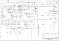
The switching module has 3 relays and a power FET transistor.
The relays are used as follows:
1) Switched by the ignition to send power to the controller;
2) Switched by the headlight circuit to provide power to the vest heating circuit after the engine is running;
3) Switched by the controller to provide contact closure across the hand gear-change select button;
The FET is cycled on and off by the controller to provide adjustable heating.
Operation.
When the ignition is turned on, the controller waits for about 100mS, then switches on the gear select relay, after another 200mS it turns it off.
The controller's heater setting switch is a 3 position toggle switch, sprung to the centre. (I wanted to use two push buttons but couldn't find any sealed ones.) Pressing the switch one way will increase the heat setting, the other way will lower it.
I have arbitrarily chosen to use 8 heat settings (on for one eighth of the time to eight eighths of the time).
When the switch is pressed, the display shows the current setting in the form "0H" for off, "1H" to "8H" when on. Clicking the switch up or down (or holding it to auto-repeat) will increase (or decrease) the setting.
When the switch has been released for a short while, the display reverts to voltage. If the voltage is low (currently below 13.5 volts), no power will be switched to the vest, periodically the display will show "0L". If the switch is pressed, the display will also show "0L".
The display brightness is something of an issue. Clearly it needs to be bright in daylight to be visible, but dim in the dark so as not to be distracting. I'd originally considered using a light sensor to modify the brightness, but in the end I made it display brightly at first turn-on or whenever the switch was activated; after the switch has been left for a short while the display changes to voltage, still bright, then after a further delay it goes dim. This seems an acceptable compromise to me.
Construction.

The control box consists of a totally water-proof box with a transparent lid so the display can be seen from the inside, and a sealed switch to control the vest.
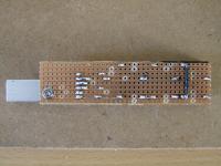
There is an aluminium plate screwed to the box's bottom. This is used both as a heat sink for the power regulator and to mount the rest. Above the plate is a piece of strip-board with the power regulator components. At the top is a piece of square-pad board on which the control circuitry is mounted, but a small piece of board is used behind the display to fix the current limiting resistors for the display segments.
The switch is through a hole in the box side; it is fitted with a sealing washer and sleeve.
A 6-core cable feeds through a hole in the bottom of the box, a grommet will stop water coming in. The box has a second grommeted hole, a left-over from a previous use of the box. I've put a tube through this and called it a breather so any damp can evaporate away.

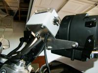
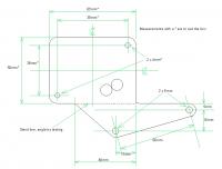
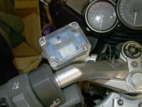
I made a bracket to bolt the box to the light and gear-change switches on the left handlebar, using spacers and long screws replacing two of the original screws. It is angled for convenient reading of the display and switch operation. I intend painting it black; it will be less noticeable and will look a bit like a clutch reservoir, more or less balancing the brake reservoir.
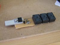
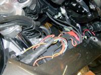
The power switching module is made on a piece of strip-board, the three relays and other components soldered to it. The power switching FET is bolted to a small piece of aluminium to allow any heat to be dissipated. The whole is wrapped in self-amalgamating tape to protect and insulate everything, the aluminium is exposed at one end to the air to allow heat to escape.
The whole module is simply placed above the battery under the panel, there is just room for it there.
The power module is wired from the battery via a fuse; all circuits are after this fuse. (Actually there are two fuses, but that's not really relevant.)
There are no connectors used anywhere (other than where the vest plugs in), they are only a source of problems. If any maintenance is required I will unsolder whatever connections are necessary.
For a fuller description, including my methods of tapping into the bike's wiring, more details of the unit's construction and links to the software, try my write-up.
I've not had a chance to use it much, but a brief trial showed everything works exactly as I want. A useful way to fill non-riding time
 .
.
Please note: I have no intention of going into mass production, it's much too (riding) time consuming, I've only posted it here in case it's of interest to anyone.
Happy new year!

(Click on image for larger view)
Since one obvious desirable feature is that it should stop powering the vest if the battery voltage is low, it seemed reasonable that it should measure the voltage. So it would be easy to make it display the voltage. And, while we're at it, it can "press" the hand gear-change select button (something I've always wanted).
What I've come up with is a control box on the handlebar and a power switching module by the battery.


The control is done using a microprocessor, It's a PIC16F873, one I've used many times before, and more than capable of the task required.
The complete circuit is here:

The switching module has 3 relays and a power FET transistor.
The relays are used as follows:
1) Switched by the ignition to send power to the controller;
2) Switched by the headlight circuit to provide power to the vest heating circuit after the engine is running;
3) Switched by the controller to provide contact closure across the hand gear-change select button;
The FET is cycled on and off by the controller to provide adjustable heating.
Operation.
When the ignition is turned on, the controller waits for about 100mS, then switches on the gear select relay, after another 200mS it turns it off.
The controller's heater setting switch is a 3 position toggle switch, sprung to the centre. (I wanted to use two push buttons but couldn't find any sealed ones.) Pressing the switch one way will increase the heat setting, the other way will lower it.
I have arbitrarily chosen to use 8 heat settings (on for one eighth of the time to eight eighths of the time).
When the switch is pressed, the display shows the current setting in the form "0H" for off, "1H" to "8H" when on. Clicking the switch up or down (or holding it to auto-repeat) will increase (or decrease) the setting.
When the switch has been released for a short while, the display reverts to voltage. If the voltage is low (currently below 13.5 volts), no power will be switched to the vest, periodically the display will show "0L". If the switch is pressed, the display will also show "0L".
The display brightness is something of an issue. Clearly it needs to be bright in daylight to be visible, but dim in the dark so as not to be distracting. I'd originally considered using a light sensor to modify the brightness, but in the end I made it display brightly at first turn-on or whenever the switch was activated; after the switch has been left for a short while the display changes to voltage, still bright, then after a further delay it goes dim. This seems an acceptable compromise to me.
Construction.

The control box consists of a totally water-proof box with a transparent lid so the display can be seen from the inside, and a sealed switch to control the vest.
There is an aluminium plate screwed to the box's bottom. This is used both as a heat sink for the power regulator and to mount the rest. Above the plate is a piece of strip-board with the power regulator components. At the top is a piece of square-pad board on which the control circuitry is mounted, but a small piece of board is used behind the display to fix the current limiting resistors for the display segments.
The switch is through a hole in the box side; it is fitted with a sealing washer and sleeve.
A 6-core cable feeds through a hole in the bottom of the box, a grommet will stop water coming in. The box has a second grommeted hole, a left-over from a previous use of the box. I've put a tube through this and called it a breather so any damp can evaporate away.


I made a bracket to bolt the box to the light and gear-change switches on the left handlebar, using spacers and long screws replacing two of the original screws. It is angled for convenient reading of the display and switch operation. I intend painting it black; it will be less noticeable and will look a bit like a clutch reservoir, more or less balancing the brake reservoir.


The power switching module is made on a piece of strip-board, the three relays and other components soldered to it. The power switching FET is bolted to a small piece of aluminium to allow any heat to be dissipated. The whole is wrapped in self-amalgamating tape to protect and insulate everything, the aluminium is exposed at one end to the air to allow heat to escape.
The whole module is simply placed above the battery under the panel, there is just room for it there.
The power module is wired from the battery via a fuse; all circuits are after this fuse. (Actually there are two fuses, but that's not really relevant.)
There are no connectors used anywhere (other than where the vest plugs in), they are only a source of problems. If any maintenance is required I will unsolder whatever connections are necessary.
For a fuller description, including my methods of tapping into the bike's wiring, more details of the unit's construction and links to the software, try my write-up.
I've not had a chance to use it much, but a brief trial showed everything works exactly as I want. A useful way to fill non-riding time
Please note: I have no intention of going into mass production, it's much too (riding) time consuming, I've only posted it here in case it's of interest to anyone.
Happy new year!
Last edited by a moderator:

")

