Gen II ground spider discussion (bench racing)

Yamaha FJR Motorcycle Forum

Help Support Yamaha FJR Motorcycle Forum:

This site may earn a commission from merchant affiliate links, including eBay, Amazon, and others.
Griff
I see a problem with what you are proposing to do. My grounding Harness is designed to take ALL the electrical loads carried by the bike's grounding system and provide an alternate path to battery negative terminal. The largest wire Yamaha uses is the metric equivalent to 16 gage. Every one of my connectors channel the electrical path to an 8 gage butt splice via 16 gage TXL wire. This 16 gage is the largest wire the connector's pins is rated for. The butt splice performs the same task that the 6 tined "spyder" does - it ties together (shorts) all the wires within that connector. From this 8 gage butt splice, I run a 10 gage SXL wire back to the battery negative terminal.

Think of it... Yamaha runs one skinny wire from spider to spider. The last one before Battery neg. is the S4 connector. My Grounding Harness adds to this with a big piece of copper wire - not take the place of it. It takes the power away from the bikes harness at each connector, so it does not allow the build up of resistance at the S4, or S6 spyders.

Also note that the S4 connector is special, it forms a Y in the path. It is fed by S3, and S6 as well as the path to Batt. S3 and S6 are plugged into my Grounding Harness and are channeling power away from S4.

Install the Grounding Harness I sent you. Check the repair work that the mechanic did in Michigan, and let the S4 plug on my harness dangle. There is enough redundancy built in, that you are still fully protected.

If you still feel uncomfortable with this, let me make you a special replacement Male connector to plug into my Grounding Harness S4 and splice into your repair. Just bare in mind, there is no room to work in that spot. You may want to leave that repair alone if it is done well.

By the way, All the wires are crimped. There is only one spot I used solder and that is at the ring terminal at the battery negative terminal. I chose to use it there "just in case" someone has a problem with battery corrosion. I bought a High Dollar "PressMaster" crimping tool rated just for the Sumitomo .090 series pins. The crimps meet Sumitomo's design specifications.

Griff, you paid good money for my product, install it un modified as per the instructions laid out on my personal website. It will not let you down.

Let me know how it turns out. :rolleyes:

Brodie

Thanks Brodie.

Assuming the splice done in Michigan seems up to task, I will do as directed. My intent was to use your harness as designed except for the missing S4 (where I was going to splice your harness into the 6 wires that are there and provide the alternate AND original path to ground). If I can safely bypass S4 and still have peace of mind, then that's what I'll do. Simple is better, especially for me :)

 
Last edited by a moderator:
I just installed Brodie's harness, and was glad to see that everything looked good--no corrosion or melted wires. Brodie suggests servicing S5, but I can't find a picture of its location. Can anyone help me find this bastage?

 
Art, I'm on the list now, but I sure hope after getting the plastic off, it will be plain to a non electrical person such as myself what plugs where. Are the OEM plugs just left where they rest or what? I viewed the pics, and even though they are good, they don't give me the specifics but figure it will be more clear when I get into the job.

doctorj

 
Art, I'm on the list now, but I sure hope after getting the plastic off, it will be plain to a non electrical person such as myself what plugs where. Are the OEM plugs just left where they rest or what? I viewed the pics, and even though they are good, they don't give me the specifics but figure it will be more clear when I get into the job.
doctorj

Doc,

Art's harness is really straight forward to install. You will see where they plug in and run to a ground. The wires are cut to lengh. The plastic reinstall is the hardest part. You will like the fit & quality of workmanship.

 
Doc

Nothing is left just hanging. The lights and fans are unplugged, and the T-harnesses are plugged into each end of what you unplug. So nothing is left unplugged. Then you run the ends of the T-harnesses to the engine and put them under a bolt for a good ground.

Art

 
Well I attacked this problem a little differently. I pulled off the black cap, pulled out the spider and filled the plug with dielectric grease. The plug and the spider showed no signs of corrosion(2006 with 100000km).

Then I put it back together, wrapped the whole spider plug with electrical tape, wrapped that with aluminum duct tape and zipped tied it at the bottom. Ain't nothin' getting in or out of that sucker.

Now time will tell whether this makes things better, worse or doesn't do a thing. My theory is that nobody thought the system was bad until it got corroded and failed. If it doesn't get corroded then it should work fine forever.

 
Friends

One of our forum members sent me a PM regarding the various fixes offered to address the marginal ground path Yamaha "blessed" us with on our 2nd Gen. bikes. I think it deserves addressing here in this open forum discussion. I tried explaining it as best I can, Art please chime in if you can add some clarity to it.

Thanks

Hey Brodie,
I've been reading about the spider bite problem and thought I'd give you a shout to see about getting one of your harnesses. Is it just one harness or are there others for grounding the headlights and other high draw items. I've read about two other harnesses besides yours. Is yours the only one necessary or should I see about getting the others as well.

Thanks for you time.

Regards,

Steve
Hi Steve

This is an excellent question, thanks for bringing it up.

There are several methods for addressing this weakness in our bike's electrical system. My method adds a secondary path back to battery negative terminal from all 6 ground spyders. It does not allow excessive current to build up resistance at the weakest point, the single pin & 16 gage wire at spyder S4 and/or S6. Mine is a single harness solution. Installation requires removal of the fuel tank, T-bar & heat shield, removal of the left side panel and sub panel under the seat and uncovering the air box. Removal of the 4 black dash panels, and removal of the left inner faring panel next to the radiator grill. This will gain you access to all 8 of the spyders on the bike. Please note, 2 of those 8 belong to the bike's various "black boxes". Since the voltages are highly regulated within these 2, and they are not a part of Yamaha's grounding path, I advocate servicing them with dielectric grease to help keep out oxidation, and tucking them out of harm's way. My harness bypasses these 2 spyders.

Art (road runner here on the forum) has a different method of addressing the problem. He has a collection of harnesses that attach to the sub harnesses leading from the high current devices and diverts much of the current to a frame / engine bolt. If I'm not mistaken, he addresses the radiator fans and the headlights. By diverting much of this current away from the bike's grounding system, the marginal spyders will be protected from a resistance fed thermal runaway situation. From what I understand installation requires removal of the same 4 black dash panels, and removal of the right and left lower fairing panels to gain access to the connections.

Either solution requires some removal of body work. It's not difficult if you are handy with tools. This FJRForum is a great resource for information concerning how to do this. Just remember to search first, or wear asbestos under armor - especially if it's friday. :p Which ever method you choose will work out well.

Some people have cut off the spyders and crimped/soldered the wires together at each location. Still others have just serviced all the spiders with dielectric grease and called it good.

I am of the opinion that you should do something as this is like a time bomb waiting to go off. Don't get spyder bit several thousand/ hundred miles from home.

Hope this helps.

:)

Brodie

 
Brodie

Good to see you posting. I hope you're healing up OK.

Thanks for clearing it up. Very good explanation.

As an added note, it has been brought to my attention that installing my harnesses only requires R&R of the lower fairings. The fan plugs are there, and you can reach up from under the front to get to the lights. Like Brodie said, You should still clean and grease all the spiders. So to do that you will have to R&R all the same panels as installing Brodie's harness.

Also these harnesses not only take the fan & lights out of the ground loop and run them directly to ground, but they also take the wire that used to go to the device ( fan & light ) and run it to ground. So the 2 fan harnesses will add 2 ground wires to the S4 spider, and the 2 light harnesses will add 1 ground wire to the S7, and 1 wire to the S8 spiders, which will ultimately add 2 wires to the S6 spider.

Ride safe

Art

 
Doc
Nothing is left just hanging. The lights and fans are unplugged, and the T-harnesses are plugged into each end of what you unplug. So nothing is left unplugged. Then you run the ends of the T-harnesses to the engine and put them under a bolt for a good ground.

Art
Just as a follow up, I got the harnesses in today and installed. They look like fine products. Even though I had not had any problems, I thought it good to do this prophylactically to have more confidence in the bike i.e. not get stranded somewhere. And I had most of the tupperware off to do other maintenance and coolant flush. Now for the tupperware reinstall :angry: . The tupperware on my two bikes are making me want a naked bike someday :yahoo: . Hmmm, now to get Yamaha to bring that 1200 Super Tenere to the USA, NICE.

doctorj

 
I hope Yamaha issues a fix for this soon cause I lost when it comes to electrical stuff...:|

 
I hope Yamaha issues a fix for this soon cause I lost when it comes to electrical stuff...:|
Just order a set from Art, and then PM me. It would be like the blind leading the blind :dribble: . Seriously, it isn't too bad at all. I did forget to add dielectric grease but that isn't too bad. I'll do that when the bike hits 100,000 mi. maybe. Since this is not a safety issue (well maybe) and not affecting large #s of bikes, I betcha Mama Yama won't issue a recall/fix, but I've been wrong once or twice in the past :rolleyes: .

doctorj

 
I hope Yamaha issues a fix for this soon cause I lost when it comes to electrical stuff...:|
Just order a set from Art, and then PM me. It would be like the blind leading the blind :dribble: . Seriously, it isn't too bad at all. I did forget to add dielectric grease but that isn't too bad. I'll do that when the bike hits 100,000 mi. maybe. Since this is not a safety issue (well maybe) and not affecting large #s of bikes, I betcha Mama Yama won't issue a recall/fix, but I've been wrong once or twice in the past :rolleyes: .

doctorj

Thanks!

 
Just out of curiousity, I decided to estimate the benefits of installing all four of road runners T-Harnesses on my FJR. I know - I need to get a life! Just thought some of you would be interested. Hopefully all of you agree with my reasoning.

Changes made to “Rev 04” calc sheet (see post #15):

- Set current coming from both Headlights and both Fans to 0 amps (each have separate ground wire now)

- Divided the total current collected at S7 by 2 (1 extra ground wire shares load on spider)

- Divided the total current collected at S8 by 2 (1 extra ground wire shares load on spider)

- Divided the total current collected at S4 by 3 (2 extra ground wires share load on spider)

ESTIMATED RESULTS:

Peak current (everything powered up), total new amperage on the individual spiders:

S1= 5.85

S3= 8.30

S4= 5.89

S6= 9.39

S7= 1.61

S8= 1.38

Here’s the old “maximum" amperage values again for reference:

S1= 5.85

S3= 8.30

S4= 40.25

S6= 22.55

S7= 14.80

S8= 7.85

The results are somewhat astounding, but make perfect sense. None of the existing spiders see more than 10 amps. Mission accomplished, in my book. Good job road runner!

Insert images...

4870606799_75fb7328f6_z.jpg


4871215572_9edc5cedf5_z.jpg


RZ,

Very nice analygy. I am glad we have knowlgedable people around this forum to share knowledge and design products for repairing these problems. I am hoping this will be the last of these wiring issues for the GenII models. I don't know if Yamaha will address the spider issue or not but it would be foolish to ignore the hazard and not get one of harnesses available for such a modest investment. Thanks for posting.

 
Last edited by a moderator:
Just out of curiousity, I decided to estimate the benefits of installing all four of road runners T-Harnesses on my FJR. I know - I need to get a life! Just thought some of you would be interested. Hopefully all of you agree with my reasoning.
Changes made to “Rev 04” calc sheet (see post #15):

- Set current coming from both Headlights and both Fans to 0 amps (each have separate ground wire now)

- Divided the total current collected at S7 by 2 (1 extra ground wire shares load on spider)

- Divided the total current collected at S8 by 2 (1 extra ground wire shares load on spider)

- Divided the total current collected at S4 by 3 (2 extra ground wires share load on spider)

ESTIMATED RESULTS:

Peak current (everything powered up), total new amperage on the individual spiders:

S1= 5.85

S3= 8.30

S4= 5.89

S6= 9.39

S7= 1.61

S8= 1.38

Here’s the old “maximum" amperage values again for reference:

S1= 5.85

S3= 8.30

S4= 40.25

S6= 22.55

S7= 14.80

S8= 7.85

The results are somewhat astounding, but make perfect sense. None of the existing spiders see more than 10 amps. Mission accomplished, in my book. Good job road runner!
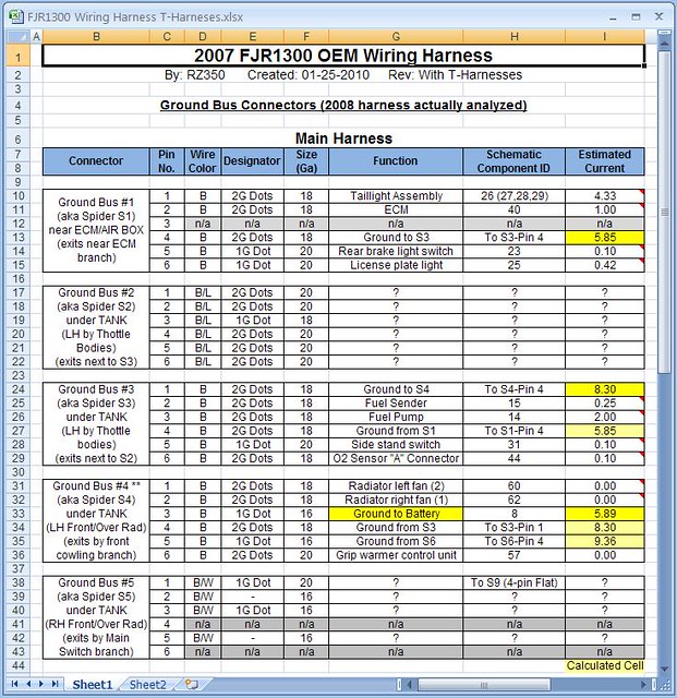
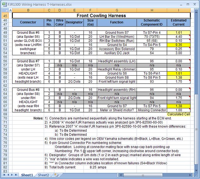
Being totally ignorant to all this, but understanding the numbers, is it so hard for Mama Yama to figger dis stuff out?? Did someone sit in front of his (or her) 3D animation computer software program and say 48 amps through that little wire should be OK... :dribble:

I recall a post from someone about Yamaha saying not to pay too much attention those misleading and misinformed forum things..... Guess I see why, all you guys must be wrong about all this...

Kudos to Art for sending me a fix so quickly. Thanks!!

And to anyone who looks at their ride and says they don't need a spider bite antidote, read my post back here - where I examined my spiders, and here, when I was stranded in Yellowstone followed by a $1000 towing bill less than a month later. This was a sudden occurrence, no warning, and could have been fatal (well, if you only drive in a straight line and never lean into a curve, maybe not fatal).

I'll post up when the dealer decides what to do with it. This may be his first YES repair.

 
Top