...RR? Not familiar with that term. It's pretty tight fishing an angled coupler thru that channel. Have a chair/table setup to hold the cover, haven't taken the stator out of the cover yet. 30 ft/lbs of torque on a T30 out/in using a torque wrench on a rounded housing lying on a table will be an exercise in leverage! Should be able to impact it out (if the T30 doesn't self destruct) but it will take a torque wrench to get it in properly. Sigh.
RR: In this context, Rectifier/Regulator.
As for the torque, to undo them I used a do-it-yourself impact wrench. Put a good quality hex key in the bolt head and tapped the arm with a hammer. Needs holding into the screw head to prevent it skewing out, and needs reseating between taps, the inertia of the stator is sufficient to stop the cover from moving much. Take your time, don't over-hit it, It will come. Of course, a proper impact wrench will do it much more easily.
Doing up, I didn't use a torque wrench, simply did the screws up until I felt they were tight enough. As far as I remember, I had a cloth on the seat of the chair, the new cover lying on it, and I more-or-less sat facing the back of the chair so my thighs were resting on the edges of the cover to stop it spinning. Used a hex screw driver bit and a socket extension to put the handle high enough to get the leverage. Must have looked very strange to any casual observer.
The stator certainly stayed in for as long as I had the bike.
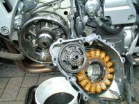
Picture below taken just after I'd pulled the cover, I didn't take any during the replacement (I was still far too angry with myself for needing to do this is the first place :banghead: ). Note the gearwheel is the wrong way round, put there just to keep it clean.
(Click on image for larger view)