Auxiliary Fuel Cell Installation

Yamaha FJR Motorcycle Forum

Help Support Yamaha FJR Motorcycle Forum:

This site may earn a commission from merchant affiliate links, including eBay, Amazon, and others.

Slonishku

Well-known member
Joined
Oct 27, 2009
Messages
87
Reaction score
8
Location
Frisco, TX
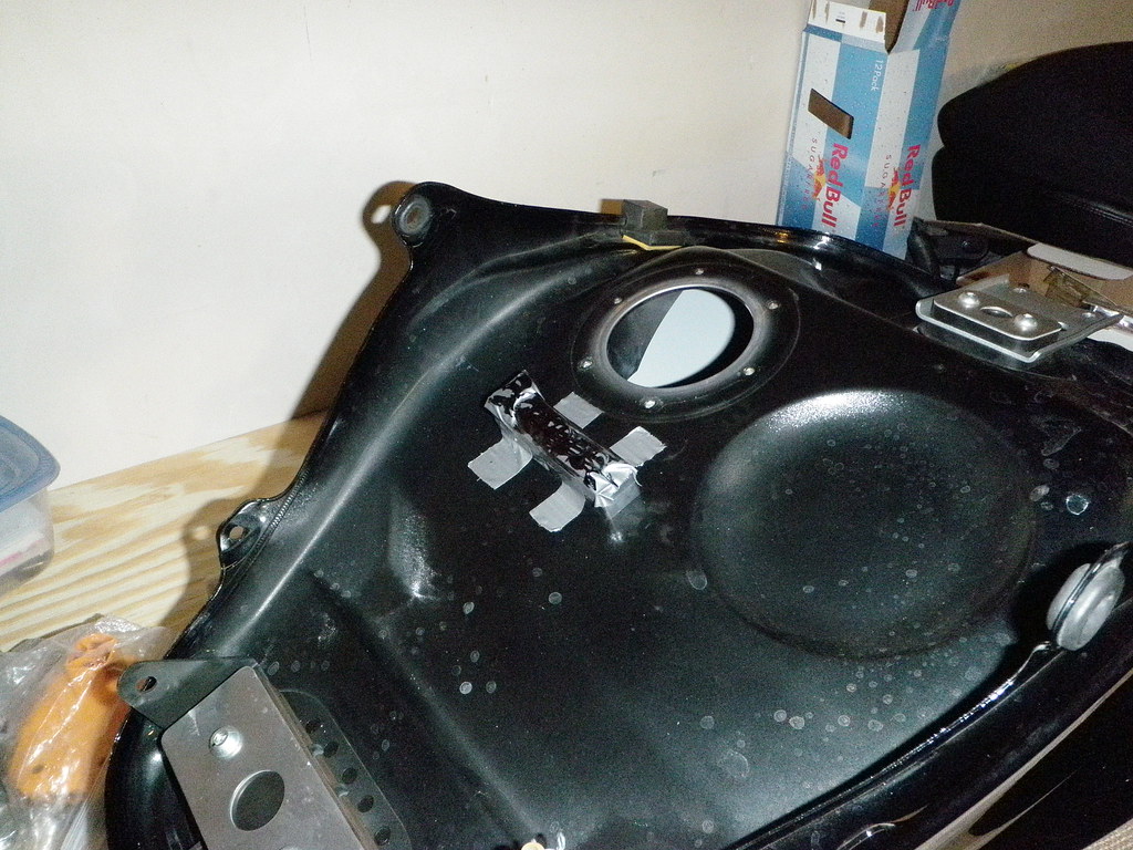
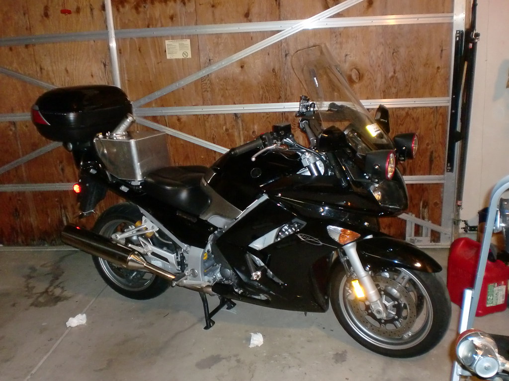
I started fitting my TAT to my FJR last week. The plan was to get it done in time to give it a local road test of a few miles, then a dozen or so miles, then ride the whole thing Bakersfield-Oakland-Concord-Bakersfield over the weekend, as I had Naval Reserve duty this weekend. I ran out of time looking for parts last week, so the Oakland ride didn't pan out.

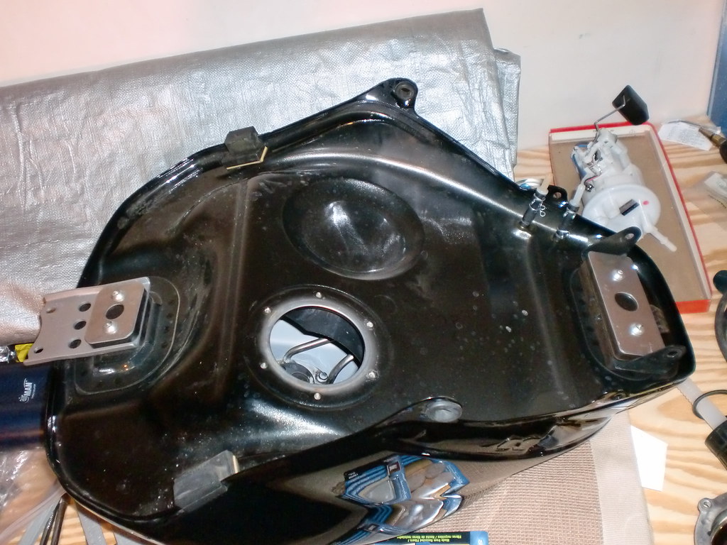
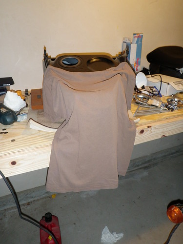
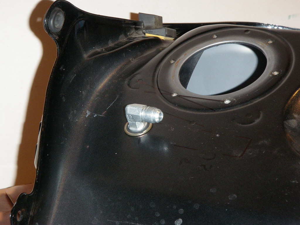
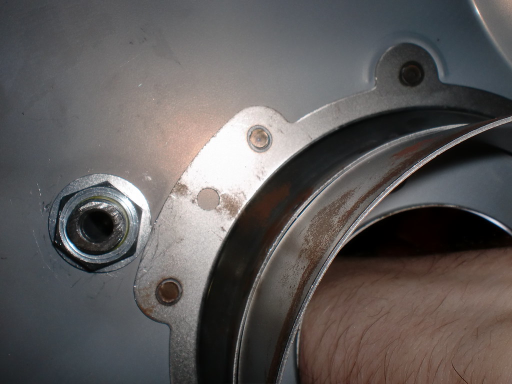
I got home sunday and finished assembly of the main tank bulkhead fitting, got everything set-up, and took the TAT on its maiden vooyage this morning (to work). I'm at work now, and everything seemed to go well this morning.

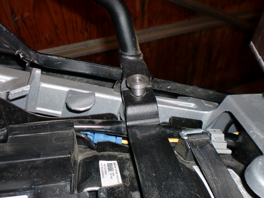
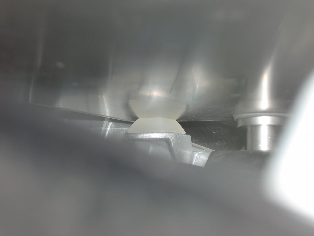
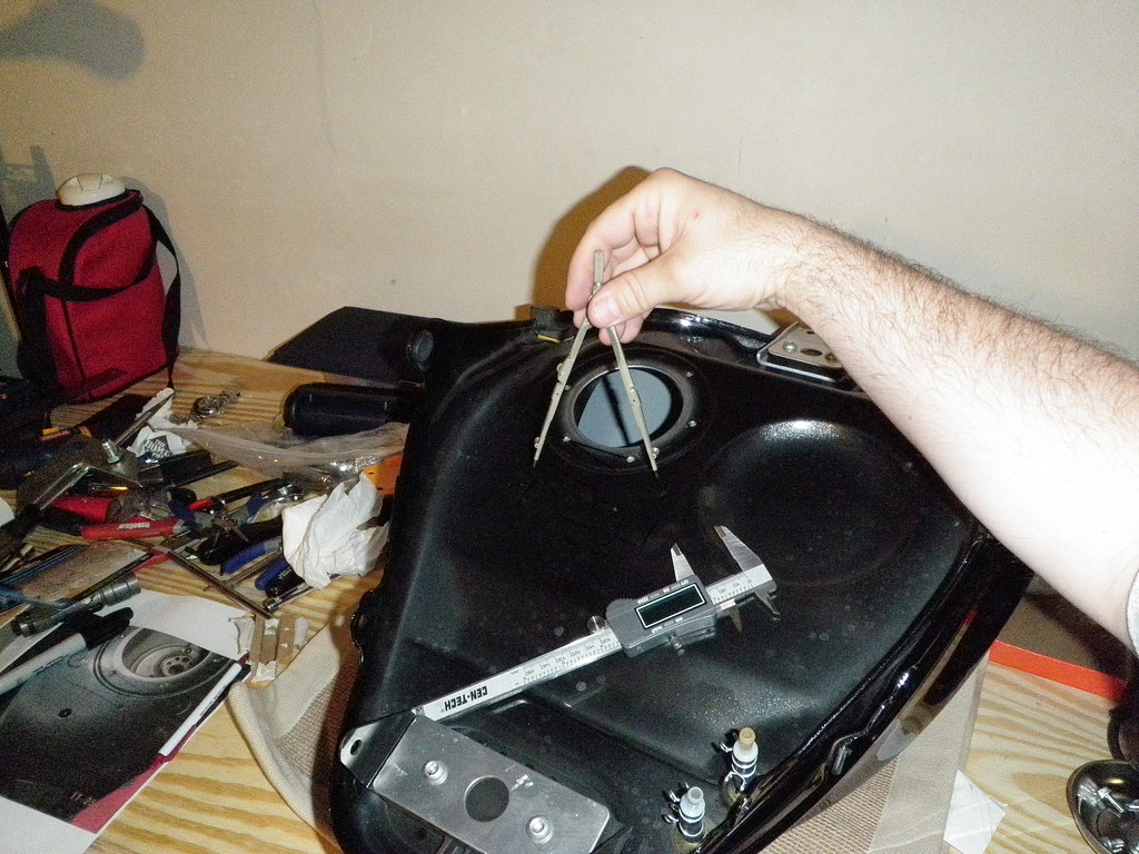
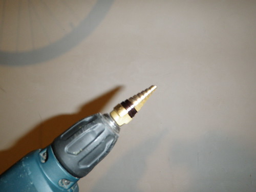
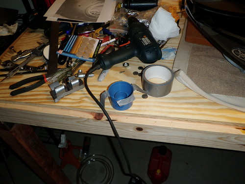
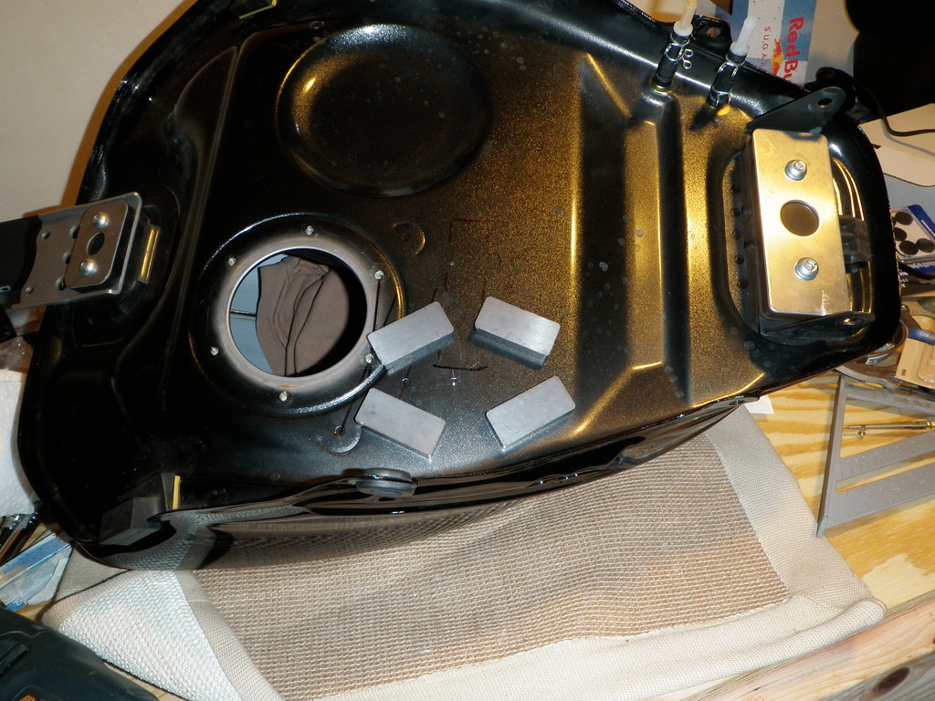
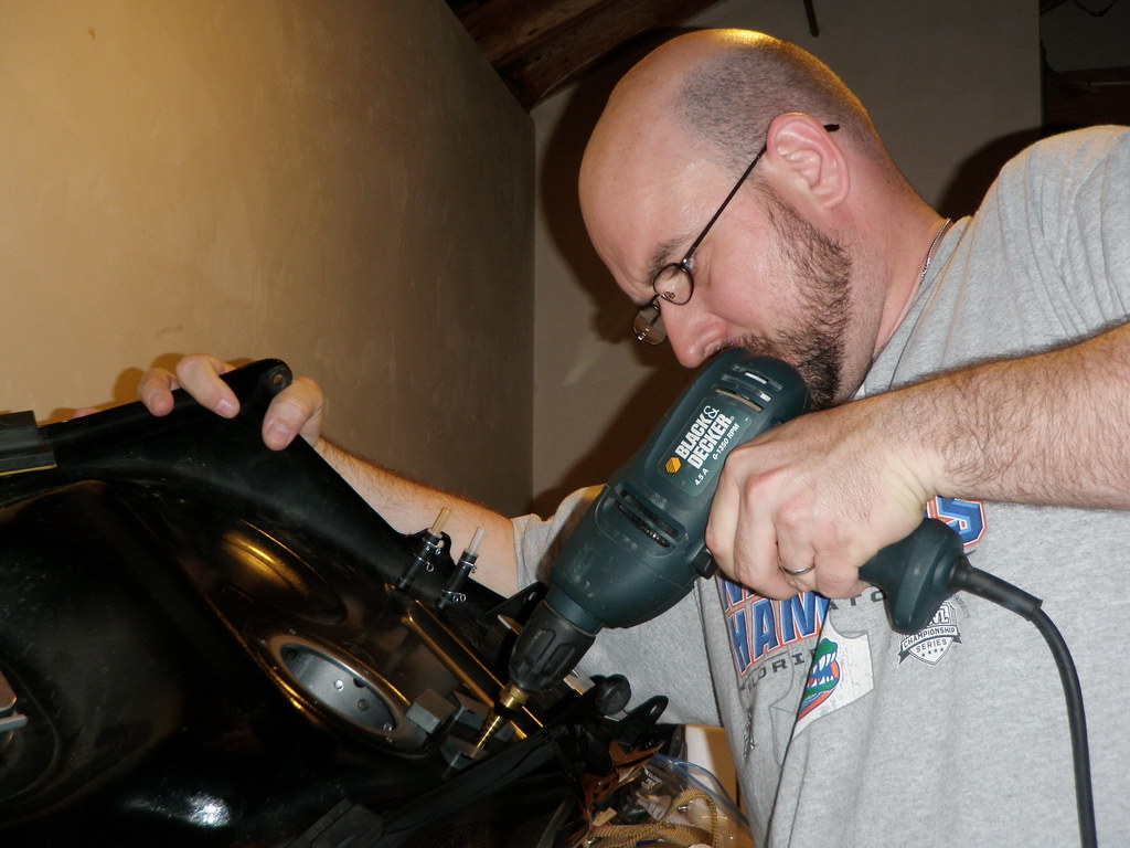
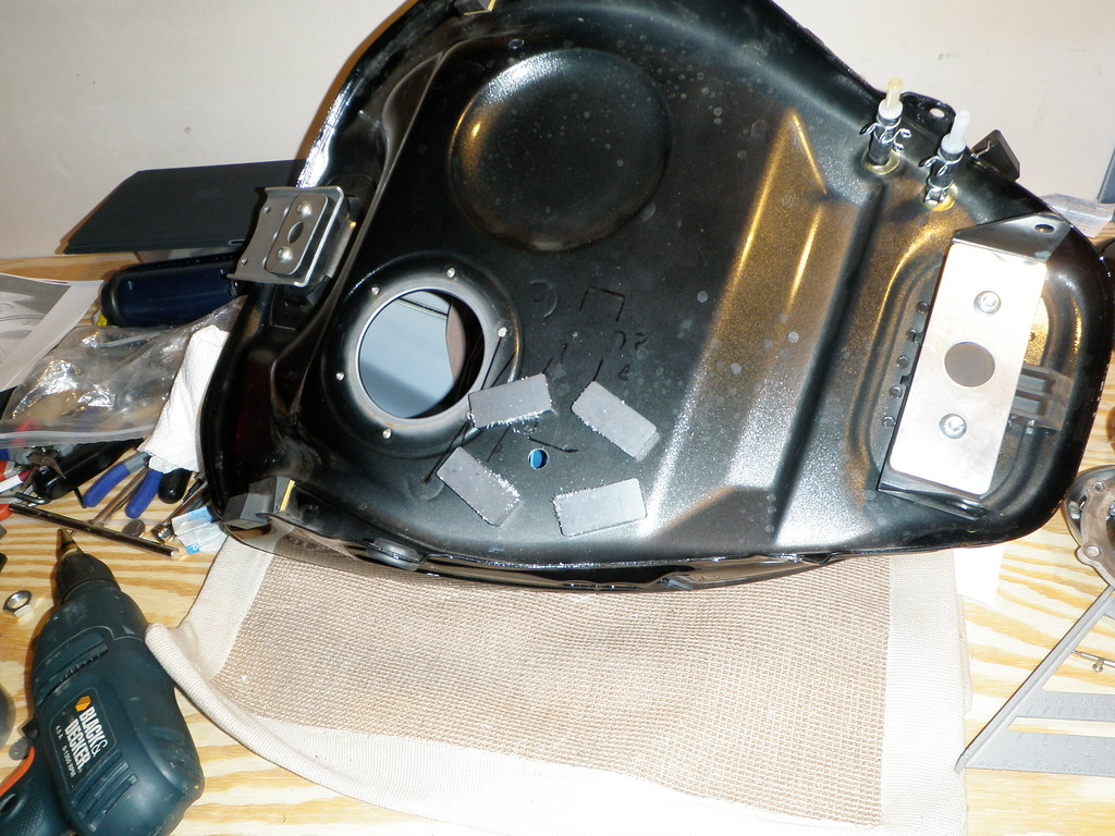
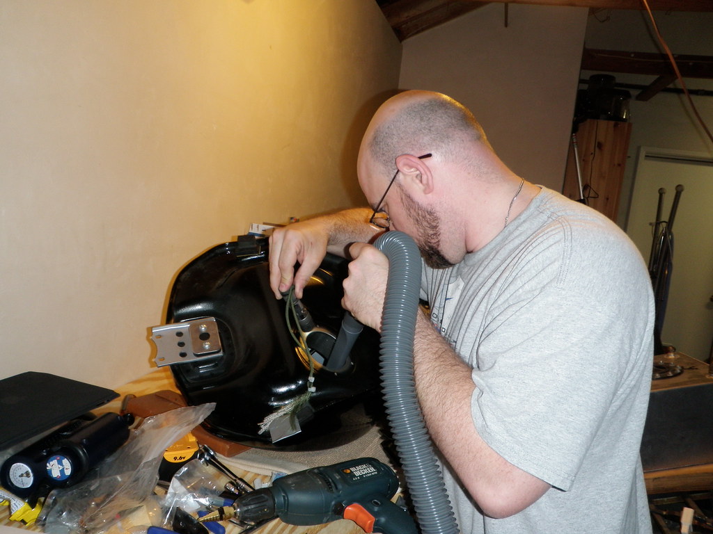
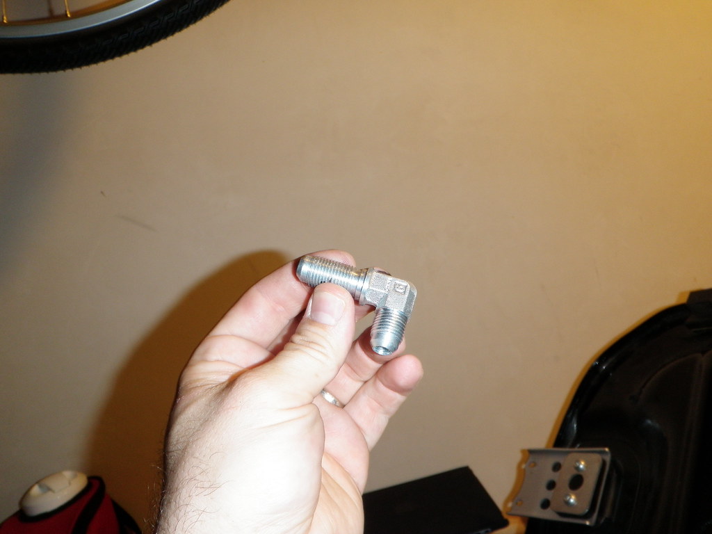
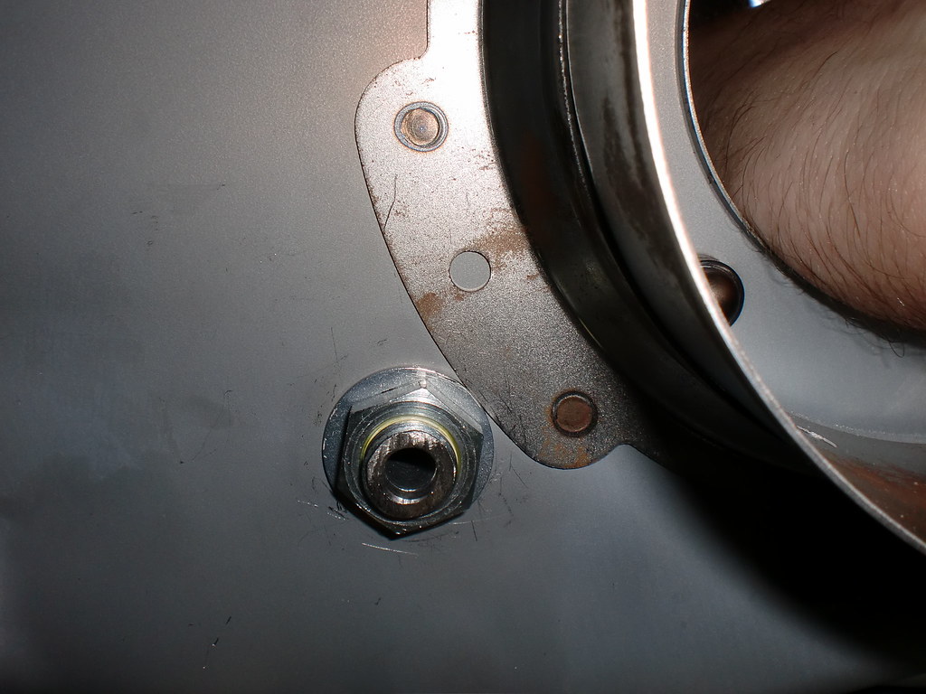
Here are some pictures from the process. I won't go into excruciating detail- just some of the more salient points.

 
To start, I'm working with a Givi topcase grabrail. As such, my factory grabrails and bushings are long gone.

The bushings supplied by Joe did come in handy, though. Since they don't fit through the bolt holes on the Givi rack, the bushings instead act as a height extension, allowing the tank to be very firmy seated without forcing the tank down against the curve of the rack's center. Forcing the tank down in that fashion would surely cause deformation of, and damage to, the tank.

Here is one of the bushings sitting in place. Note that the TAT is designed to rest on six points- the bushing attachment points are in the middle of the tank. The front of the tank rests on the passenger seat support seen on the right edge of the picture. The rear of the tank rests on the footpads seen to the left of the bushing in the picture.

4663098339_9d784fbc62_b.jpg


Because of the bushing/ Givi rack interface, the tank did not sit firmly agains the fore and aft support points as designed. The front "legs" of the tank hvered 2.47mm above the FJR's seat support. The aft support points of the tank hovered 6mm above the rear footpads. The tank itself, hovever, was solidly held in place by the bolt mounts without any wiggle or movement.

I replaced the existing 8x25mm buttonhead bolts with 35mm allen heads to accommodate the bushings and tank.

Front legs and 2.47mm gap (looking aft from the right side of the bike):

4664096400_d3c455b6c8_b.jpg


Right bushing and 6mm rear gap (looking slightly aft from the left side of the bike):

4663095063_17b835dfb3_b.jpg


To close these gaps, I made a trip to the local hardware store (OSH... Home Depot and Lowes weren't much help here). There I got an assortment of adhesive rubber cabinet door bumpers and furniture leg pads.

The rubber bumpers were just over 6mm in height and compressable with some effort. I used them for the rear gap, and they did the trip very nicely. In place, you can see that the rubber is slightly compressed from the bulged lines. There's a soft rubber washer between the tank and the bushing for shits & giggles:

4663720294_e4d5cffdce.jpg


4663721054_754dc4f4bb_b.jpg


Last edited by a moderator:
To close the front leg gap, I used felt-like furniture foot pads made of a dense recycled plastic matrerial. Again, compressable with some effort. Uncompressed, they were a bit over 3.5 mm think, but compressed nicely. There is a very thin foam rubber adhesive disk on the frame itself that I was experimenting with at first. It was left in place- that's what you see toward the front of the felt disks in the second photo here. The "felt" pads are stuck to the legs of the tank itelf.

4663098063_bab25b8559_b.jpg


4663099487_1bcdb30f94_b.jpg


Fuel pump removed, getting ready to clean the inside of the tank. Once completely clean and dry, the tank was allowed to air overnight. On the second night, I repeatedly blew the tank out with 100psi air and vaccuumed out any debris.

4663721692_bc10d57f26_b.jpg


Rather than re-invent the wheel, I looked over how and where others had chosen to mount their main tank bulkhead fittings. I explored a number of options and test fit numerous magnetic blocks to simulate the volume that would be taken up by the fitting on the underside of the main tank. I used a variety of ceramic magnet blocks from Harbor freight. They were held in position by tight applications of duct tape to prevent misleading results due to sliding. The black on the duct take is Sharpie ink. I would slather the ink on, then quick seat the tank to ensude contact with the FJR's heat shield was not too great.

4667883615_e1876b1aa2_b.jpg


4668516874_4eb77d0fa8_b.jpg


Last edited by a moderator:
Hi Slonisku, I'm curious why you didn't attach the pads to the tank itself? What happens when you want to put the passenger seat back on....do you replace the pads? Looks like you've got enough extra pads to do that but seems like a PITA. IIRC (?) those front legs are drilled to accept some sort of rubber bumper that Joe ended up not including with the tank.
As for the rear pads, I actually thought about that. It was more a matter of ensuring the pads were in EXACTLY the right spot. By applying them to the FJR's footpads, it was a guaranteed bullseye without any measuring or potential for missing the target altogether. After the tank has been on for a while, the exact spot should be clear from the resulting "clean spot" on the tank itself. At that time, I'll apply the pads to the tank rather than the bike.

I did get some of the rubber bumpers with the slotted pull-thorough sort of cone for the front feet. You are right that the front legs of the tank were drilled to accept such bumpers. The problem was that I could find no such bumpers of the right thickness. My options were either +/-1.5mm or over 6mm in thickness- neither a good option. While I'll be on the lookout for some of the correct thickness, the felt options seem to be a great fit.

 
To double check my placement of the bulkhead fitting, I studied the photos of Hal Risser's bulkhead installation (he installed a Sampson tank a while back). One of his photos was a direct shot of the underside of the tank with the hole drilled. I scaled that photo to be actual size, printed it, and used it as an overlay. Our drill points were almost exactly the same.

I did adjust my drill point to be closer to Hal's as I had originally forgotten to consider the fact that there's a flange that extends along the bottom of the tank. The flange is part of the fuel pump shroud that stabilizes fuel flow arounf the pump. That shroud is attached by spot welds to the bottom of the tank, and extends along the outer radius of that shroud among the bottom of the tank. If you look at the bottom of the tank, I believe the subtle dimples that form a half-circle around the aft of the fuel pump seal are the sites of those spot welds. In any case, it is important to be sire that there's enough room around the bulkhead drill hole to allow any internal fitting elements (i.e., jam nut and washers) to seat flat agains the inner surface of the tank without being lifted on one edge by this flange, thus compromising the seal and allowing a fuel leak. I'll post some clarification pictures after I get home tonight.

Here's the printout of Hal's tank being used to calibrate mine. You can see where I drew reference lines on the picture and my tank, using those spot weld dimples for reference points. Since my printout wasn't EXACTLY actual size, I compared angles of these reference lines as well as relative radius distances, drawn with a compass, to determine the location of Hal's drill spot on my tank.

4667890565_5f81d703bc_b.jpg


4667887187_0bd608e9bf_b.jpg


4668513130_28361c97d1_b.jpg


The Big Drill

All this done, it was time to drill. In order to assuage my nervousness over putting a hole in my pretty black tank, I took several steps. I reminded myself that many serious knuckleheads had successfully done this before me. I called myself a pussy for being nervous about it in the first place. I practiced drilling a few pieces of scrap metal, then test fitting the bulkhead fitting to those practice pieces to really ensure that I was drilling the right size of hole.

Best of all, I realized the consequence of botching the drill: I would have an excuse to take the tank to a welder to have a proper threaded bung welded in place, which is probably the best idea in the first place.

So I got everything in place... I marked the drill bit at the "one step too far" level for easy visual reference. To keep the edges of the hole smooth and consistent, I didn't want to have to stop and start repeatedly.

4668518622_a87c9055ce.jpg


I taped a spraypaint can lid inside the tank, against the drill site, to catch metal debris.

4668522174_42a53fe37e.jpg


I spread a t-shirt along the inside of the tank to catch additional metal shavings (photo from right before it was put in) (that's what she said):

4668520374_d6b0fc87b0.jpg


And put magnets around the spot to be drilled to catch even more shavings:

4668524018_b4338dc1db_b.jpg


Me drilling:

4667901119_7f44f85540_b.jpg


The magnets did a good job of collecting metal shavings. There was some, but not a lot, in the catch cap inside the tank. Essentially none fell onto the t-shirt, and only a few flecks were left in the tank when all was removed.

4668527626_55084b0e31_b.jpg


Alternating compressed air and a shop vac, I got the tank completely free of debris. Worth noting, most of the debris consisted of small bits of skin shaved from along the sides of my hand each time I pulled my hand from the tank. The inside of the puel pump openning is sharp, and I have big bear paw hands. You can see an abrasion on my hand here at the base of my thumb. There's a matching one on each hand now...

The fuel cell in the background is the one sitting on my RE5 used in the Iron Butt Rally last year. :rolleyes:

4668531212_c7d6f78ddd_b.jpg


Last edited by a moderator:
The bulkhead fitting I used is a steel one obtained at a local industrial hydralic repair shop. The long end goes in the tank, the short end is an AN-6 fitting. The part going into the tank was entirely too long. It's height above the bottom of the tank would serve only to slow flow rate and potentially impede full draining of the aux tank, as the effective relative height of the bottom of the aux tank above the bottom of the main would be reduced. In other words, the height to the bottom of the main tank is effectively RAISED to the whatever height this fitting reaches. I didn't need all that thread, so I lopped some of it off. You can see the beginning of the hacksaw cut projecting out below my thumb.

Once cut down, I openned and smoothed the top of the in-tank portion with the same step-drill used to drill the tank hole.

4668532884_854f73b2d1_b.jpg


This is a test fir of the bulkhead fitting. I didn't use the pictured oil seal washer in the final installation. I need to upload the remaining pictures tonight of the final fitting. For now, it's time to go hop on the bike and go home.

4668536328_338f2ac162_b.jpg


Last edited by a moderator:
Hi Slonisku, I'm curious why you didn't attach the pads to the tank itself? What happens when you want to put the passenger seat back on....do you replace the pads? Looks like you've got enough extra pads to do that but seems like a PITA. IIRC (?) those front legs are drilled to accept some sort of rubber bumper that Joe ended up not including with the tank.
I think we were both surprised by the Givi rack.

As soon as I learned that Slonishku had a Givi rack, I offered a few suggestions on the install. I'm pretty sure I have a solution. I just need to find a little time to make them for him.

The problem was that I could find no such bumpers of the right thickness.
There "right thickness" will just be temporary anyway. If he can get by using bumpers with his Givi rack for just a little while, I'll make him some razzle dazzle parts for the long term. He can be the Givi rack guinea pig and help me figure out these mounting problems. Guinea pigs get steeply discounted, sometimes even free parts. Everyone else should keep in mind that Givi racks add a few problems for the Tag-Along Tank and the solution will cost a few extra bucks.

 
I should have mentioned that fact- Joe has been answering questions and offering solutions all along, and it's greatly appreciated.

 
Here is the fitting set-up. It's the above mentioned steel elbow fitting, jam nut, Sat-O-Seal aluminum/ viton washer, and an AN-6 aluminum barb fitting.

4680822963_b5d673630b_b.jpg


The threads were wrapped in fuel-type teflon tape

4681459760_c8c0cf3a11_b.jpg


A couple of photos of the inside of the tank with the fitting in place. Note that the fitting is precisely the minumum distance from the shroud flange- the washer is right up against it.

4680833011_660ecfc17c_b.jpg


4681467882_d794b8ec3a_b.jpg


And here the tank is in place...

4681472238_d67288651e_b.jpg


Last edited by a moderator:
This morning on the way to work I put a small amount of gas in the main tank-maybe a quart to half a gallon. I rode to the nearest gas station, where I put 4.7 gallons in the fuel cell and openned the valve. While riding, the feul indicator stayed flashing on reserve for several minutes. Then the LCD display shoed a single solid bar. About two minutes later, a second bar appeared. A few minutes later, a third. I got to work, put the bike on the center stand. After work, the fuel gauge indicated four bars. It appeard that the fuel had found its level between the main and auxiliary tanks. Back on the road, the fuel indicator peaked out at five bars, then settled back to four.

It's pretty clear that, even cruising along at about 80mph, fuel was flowing into the tank much more quickly than it was being consumed by the motor.

Tomorrow, I'll continue using the existing fuel.

 
I still have a few things to do with this fuel cell. I think several folks with Tag-Along-Tanks are going to be talking to Linda T about making custom covers for the cells, and I'll probably look to get in on that. The other main thing is to make a shield to skirt of some sort to enclose the area under the tank just to keep things a little cleaner.

As of this morning, all still appears to be working as intended. I should be riding the Cal24 rally this weekend and giving the tank a real solid shakedown cruise. I might even by the first to complete an IBA certified ride using a TAT...

 
Nice write up and job. I still haven't installed my TAT (many FJR projects happening concurrently) but having your visual roadmap will help when I do.

Just curious as to why you chose to point your 45° filler neck forward -v- to the right of the bike?

 
Nice write up and job. I still haven't installed my TAT (many FJR projects happening concurrently) but having your visual roadmap will help when I do.
Just curious as to why you chose to point your 45° filler neck forward -v- to the right of the bike?
I've heard way too many stories of folks getting tired and leaving the gas cap behind during rallies. This way, the filler neck is pointed foreward and will whistle like a jug if I get up to speed with the gas cap missing.

 
Top