Had a chance to go for a test drive this past weekend after I installed my Audiovox CC. Thank you Smitty for the great tech tips, <SNIP>I've kept records and lots of pics on my install. <SNIP>
Gordon from S.F., CA.
O K Gordon, in addition to
https://www.fjr1300.info/howto/audiovox.html
for us guys & gals who are about to undertake this job, what additional tips & pixs do U have for us that will make it easier for us.
Thanks,,,De

Hello fellow FJR owners,
I’ve had some requests to post the highlights and areas of interests of my install. You will see below that some areas have deviated from previous installs. I’ve made some changes to streamline and or to minimize modification to the factory stuff. I hope this will help to assist those who are interested in installing the Audiovox CCS-100.
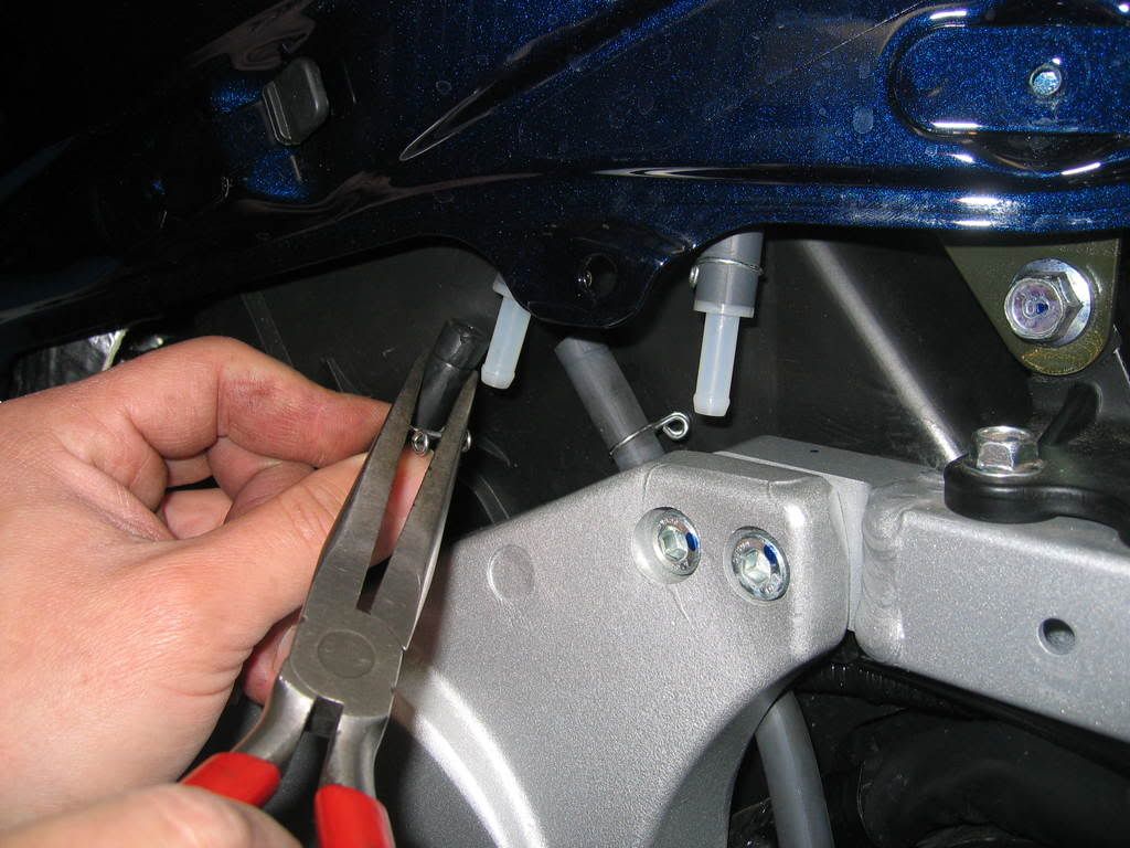
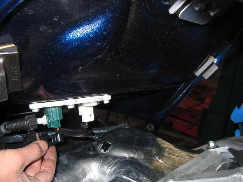
In order to remove gas tank, you will need to remove two vent hoses on the left side.
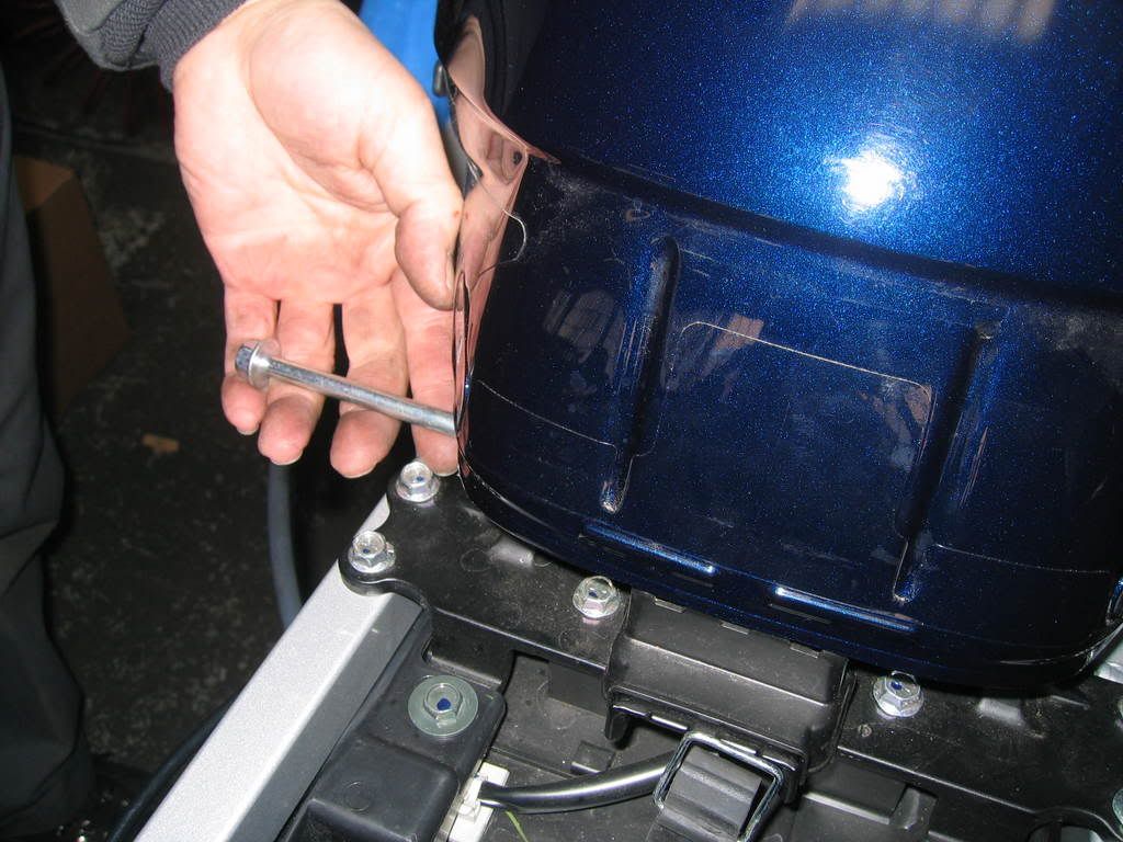
Remove allen bolts in front of gas tank and loosen nut and thru bolt in back of gas tank. Do not remove thru bolt at this point, this will help you to tilt the tank in order for you to remove electrical connectors and fuel line. Notice the plastic fuel line safety securing piece that need to come off first before fuel line can be removed.
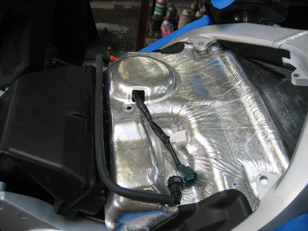
This is what you see with tank removed.
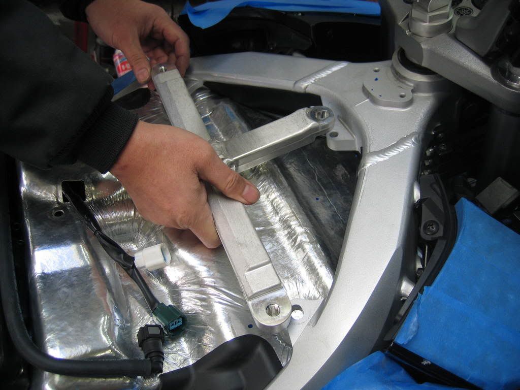
Remove 3 bolts and frame brace.
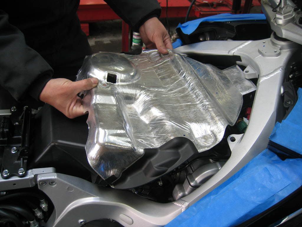
Remove heat shield.
Remove air valve by loosening 3 hose clamps and electrical connector.
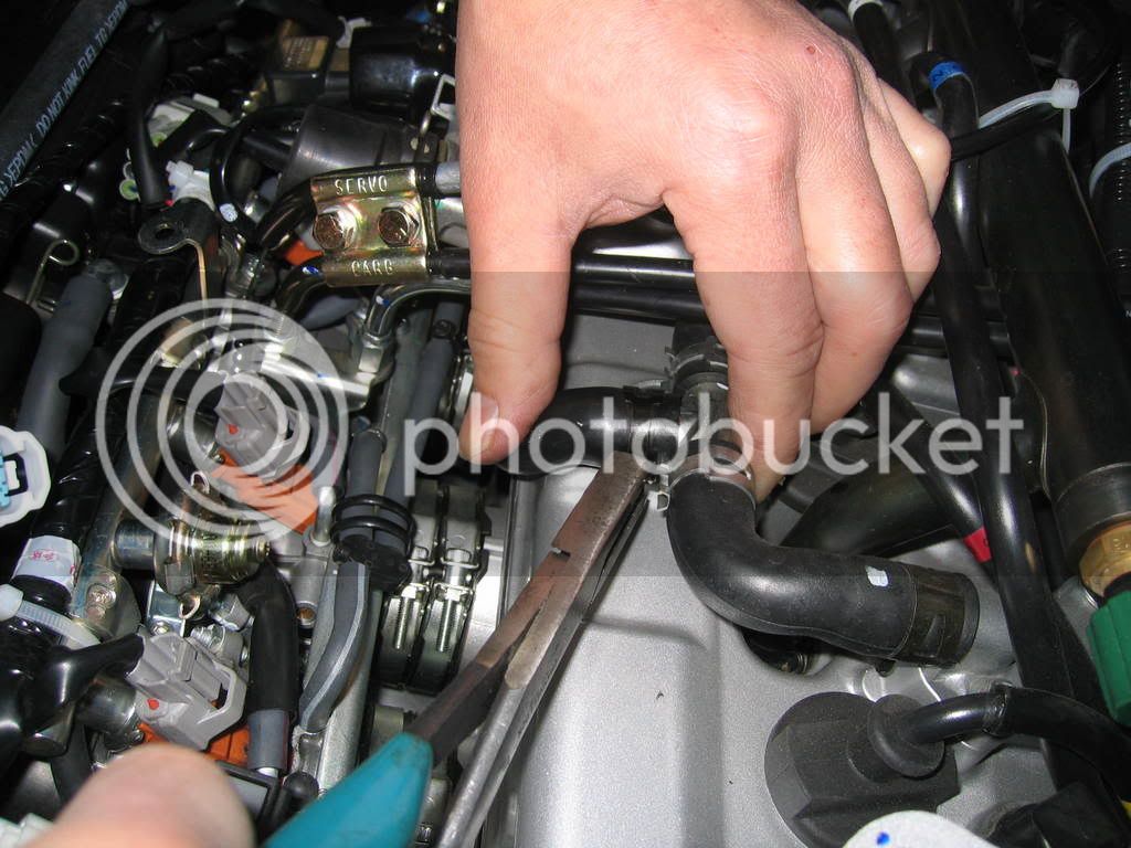
Disconnect idle speed adjustment cable from retainer grommet located below right front frame between engine and frame.
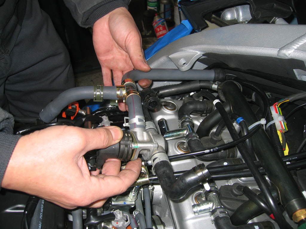
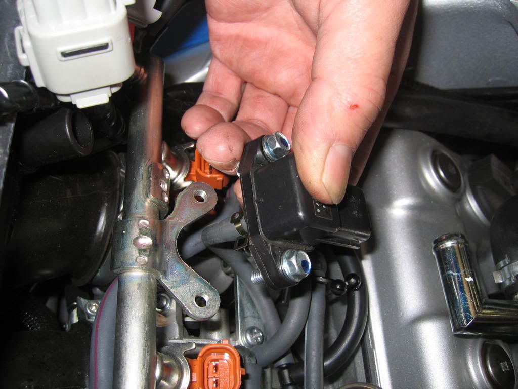
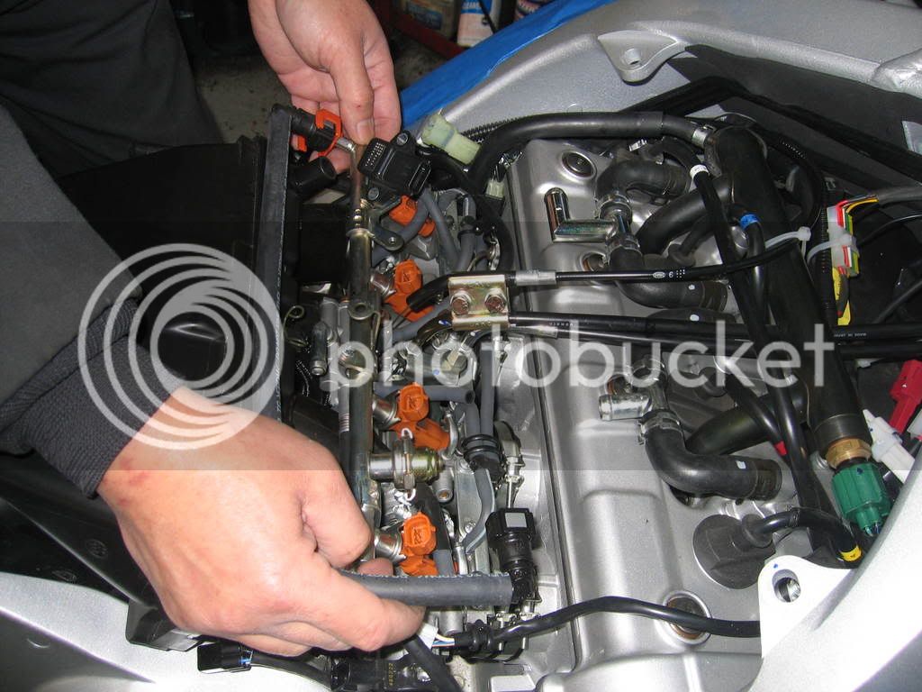
Remove 2 bolts to the fuel system MAP sensor off the injector rail.
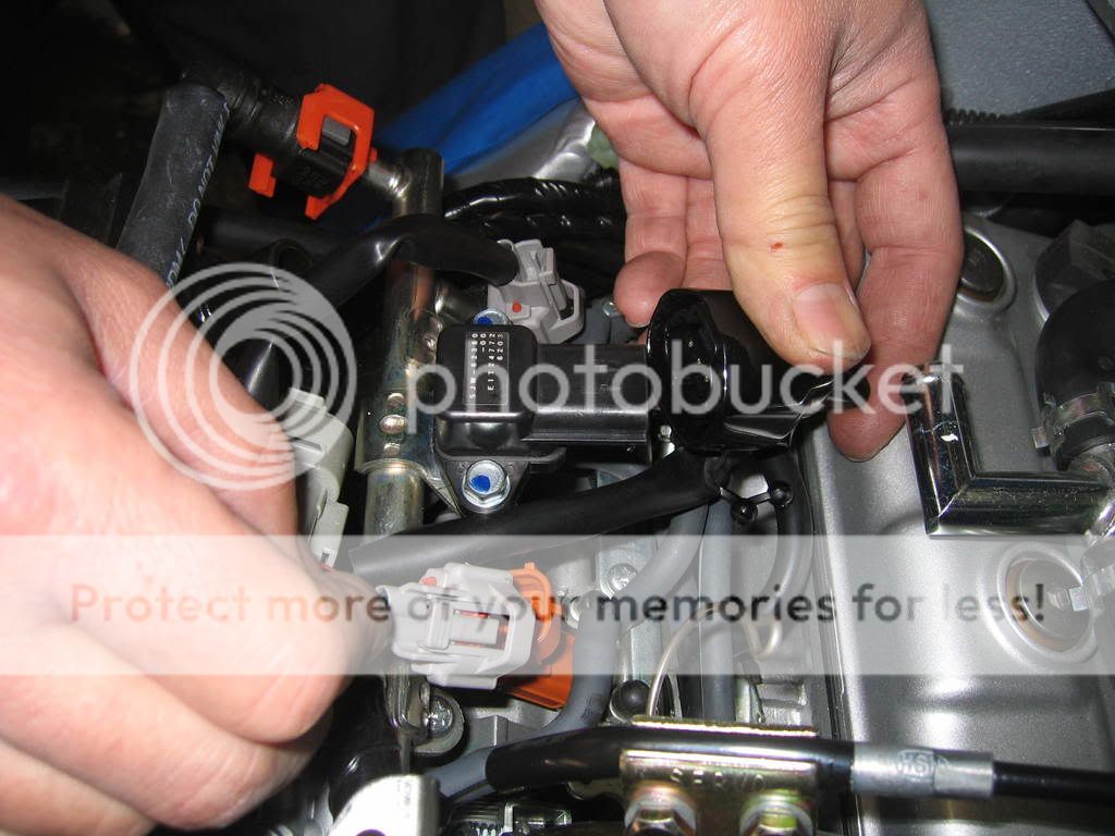
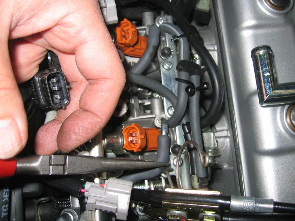
Disconnect electrical connector to Injectors, MAP sensor, Throttle positive sensor etc… and move entire harness to left side of the bike and out of the way.
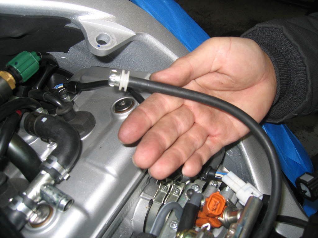
Disconnect vacuum hoses from fuel rail assembly.
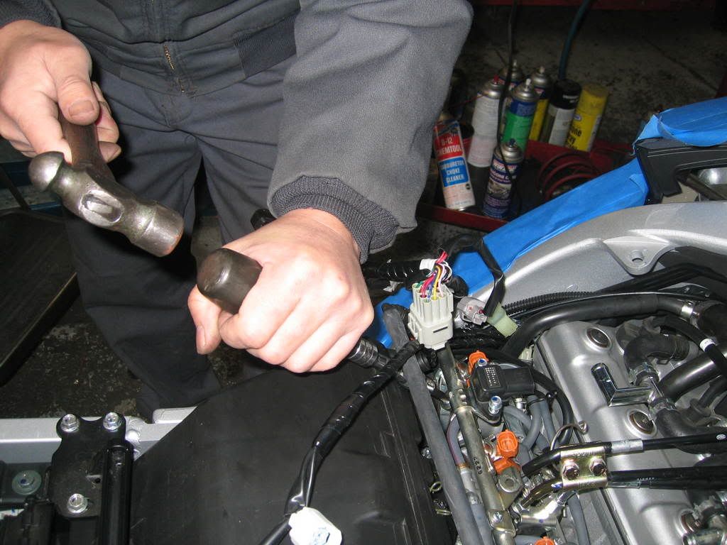
Remove 2 screws and spacers securing fuel injector rail. These screws are tight, I had to use an impact driver in order not to damage them.
Remove fuel injector rail with injectors, be careful not to drop the o rings at the tips of the injectors.
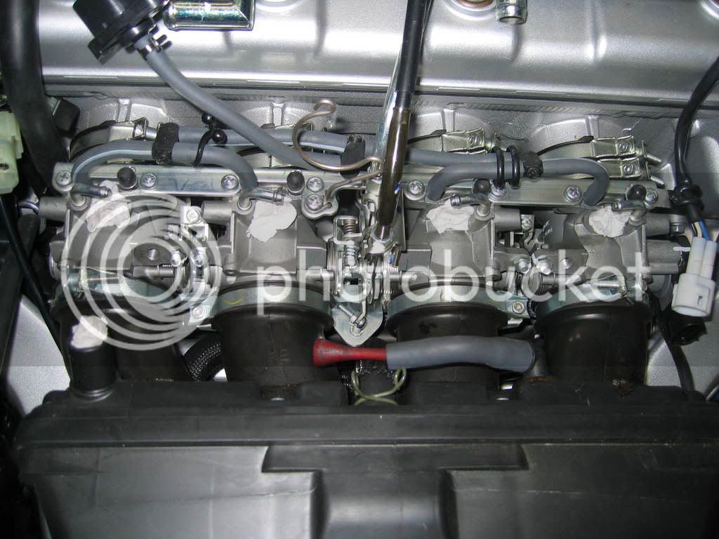
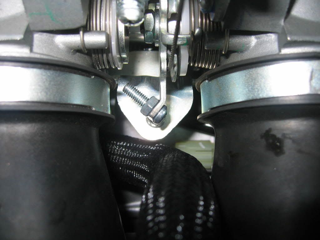
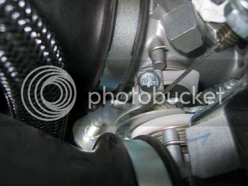
Drill hole for 4 mm bolt to install on throttle pulley tang and install bolt and nut with lock tight. I used a spring loaded auto center punch to put a nice dimple onto the tang so my drill bit won’t wander. Do not use a regular center punch with a hammer here, you will bend the tang and it will not be aligned with the idle speed adjusting screw after. This is a small hole with little material to work with. You don’t want to drill off center here. Take your time, it may be helpful to have somebody hold the throttle open to a position for a straight shot with the drill.
Use a low profile button head allen bolt to avoid touching and or hanging up on the factory throttle cable, the clearance is very tight. Test this many times to be sure!!!!!!
As you can see from the pictures below, I did not use a button head allen bolt because I did not have one. Instead, I ground away a portion of a 4mm Phillips screw for this reason. You could do this as well, just be precise. FYI, Smitty has the correct bolt and he was nice enough to offer one to me but I was too impatient to take him up on it.
Prepare the servo unit for installation: (sorry I don’t have pictures for the next few steps)
1) Remove the 2 screws holding the access cover in back of the servo unit and remove cover.
2) Remove main wiring harness. Note what position it came off. Although there’s a locking tang, it does not look totally fool proof.
3) Cut off and discard the separate harness (wrapped together) grey and black wires. Only cut the wires that are wrapped together and not the bigger black wire in the main connector of the servo unit harness. This is only used for vehicles with VSS (vehicle speed sensor). Since we will be operating on engine speed only (tach signal) this will not be needed.
4) Set the 7 dip switches inside the servo unit as follows: #1, #4, #7 in ON position. #2, #3, #5, #6 in OFF position.
5) Reinstall main connector and resecure cover. Make sure wires are spread out in order to have good seal.
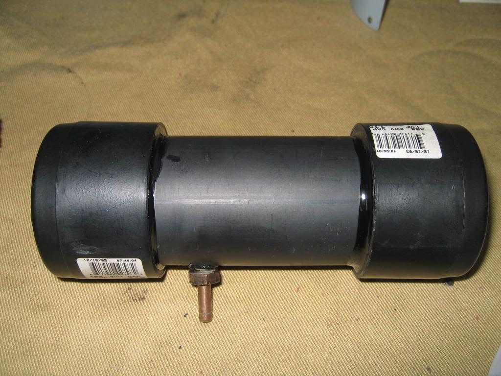
Fabricate vacuum canister: I used 1 ½” ABS drain pipe with end caps and a brass fitting. All available from your local Home Depot or Lowes.
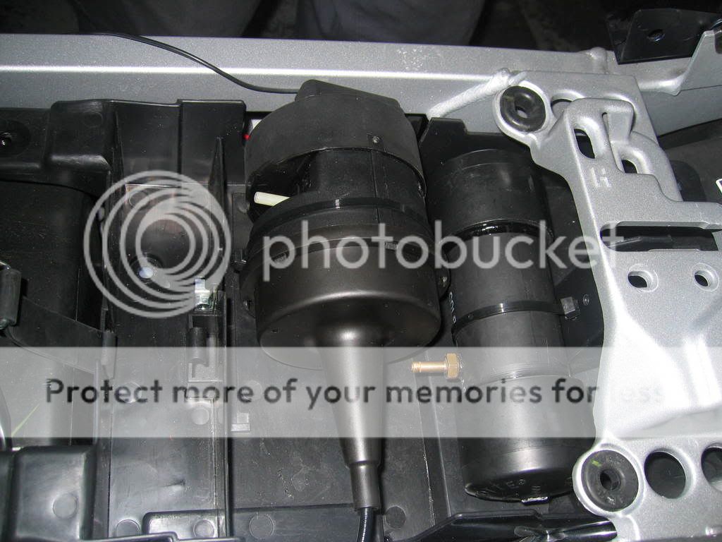
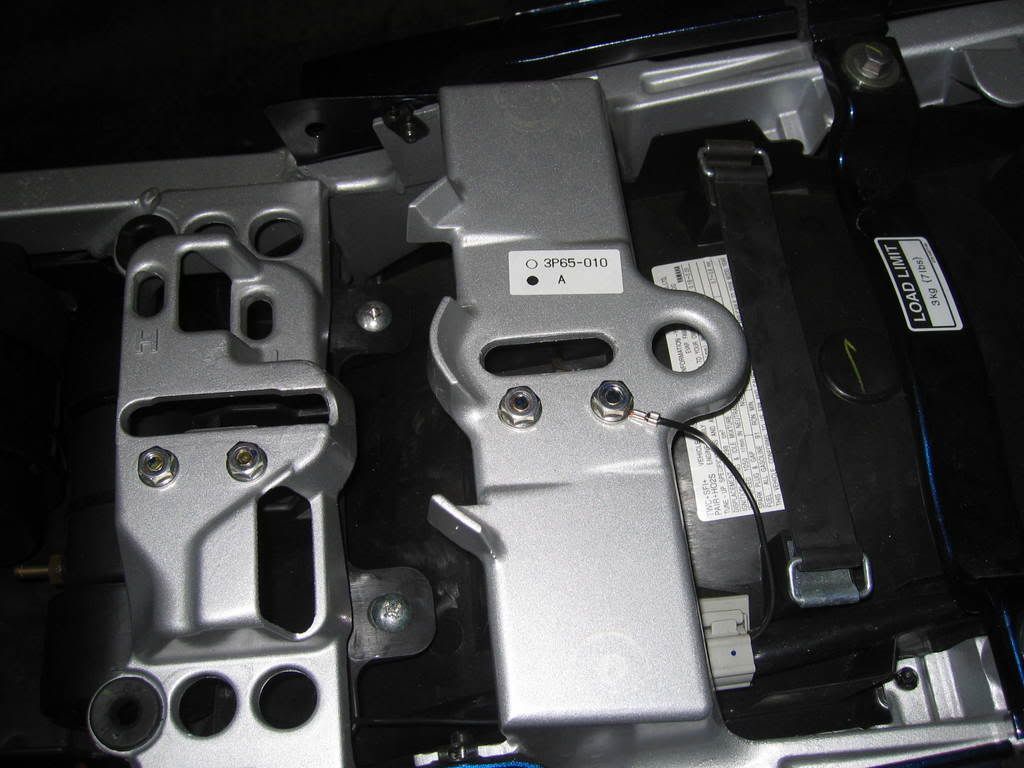
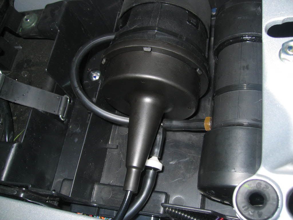
Prepare storage tray for servo unit and vacuum canister: Notch the right side for the servo unit to sit properly. Drill small holes to accept tie straps to hold both units in place. Be careful here, the computer is mounted under tray. I removed the entire tray to avoid any chances of damaging computer. Secure servo unit and vacuum canister. Route the cable along left side of frame and back down center of engine toward throttle pulley.
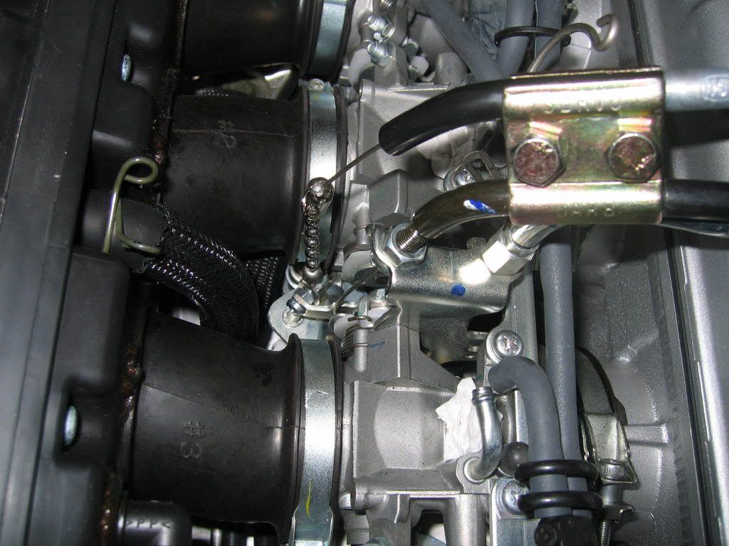
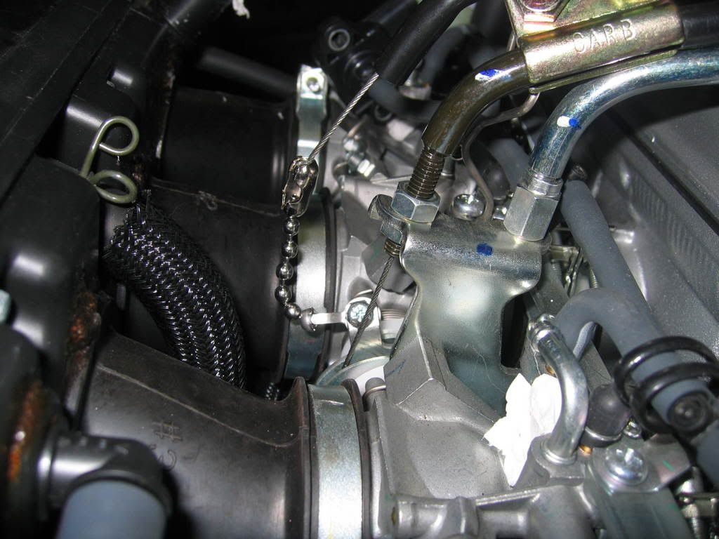
I made a cable guide sleeve to reduce the steep angle between the end of the servo cable to the throttle pulley. I used a piece of hard plastic automotive fuel line and used a heat gun to soften it for the bend. It fitted perfectly over the metal threaded cable end.
Cut off 7 bead of the chain and attach connectors to both ends of the chain. I used a small piece of shrink tubing over the servo cable connector after crimping as an extra precaution (it’s not in this picture).
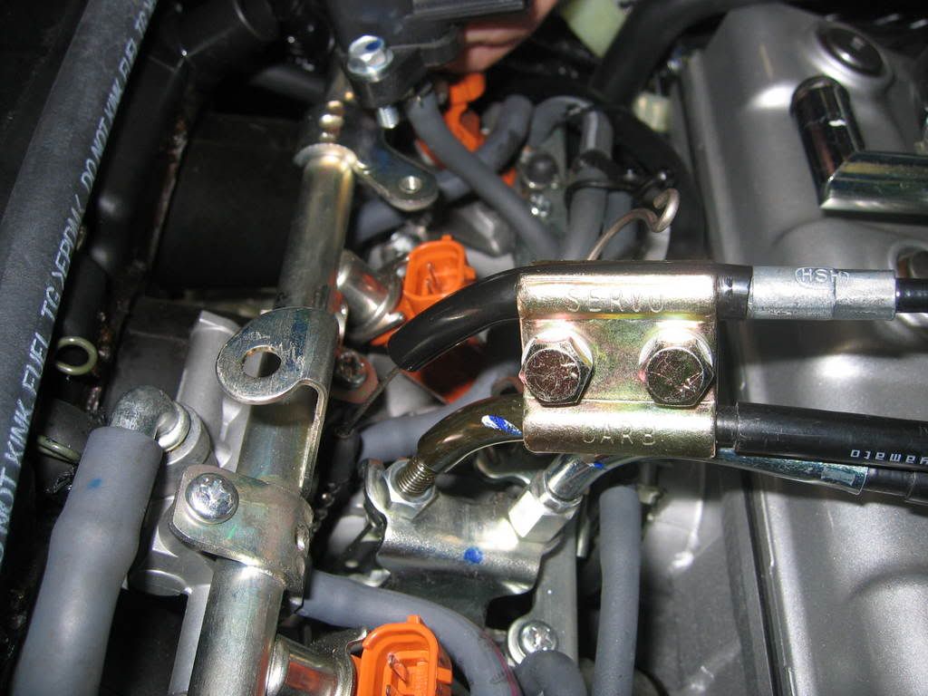
Attach cable to throttle pulley bolt by using 2 nuts with lock tight compound.
Secure cable with supplied bracket. You will need to adjust the position for best fit and cable free play after installing the injector fuel rail and other surrounding components.
Operate throttle and make sure cable/pulley combination will clear all surrounding parts without any hang ups. This is very very very important!!!!!
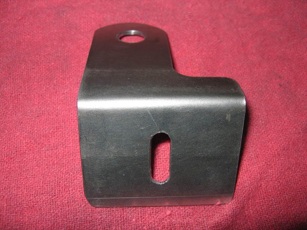
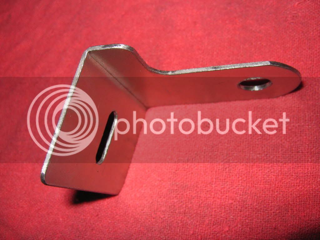
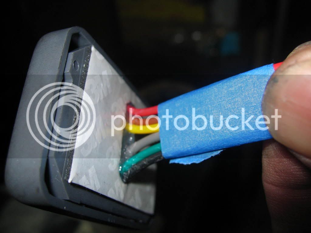
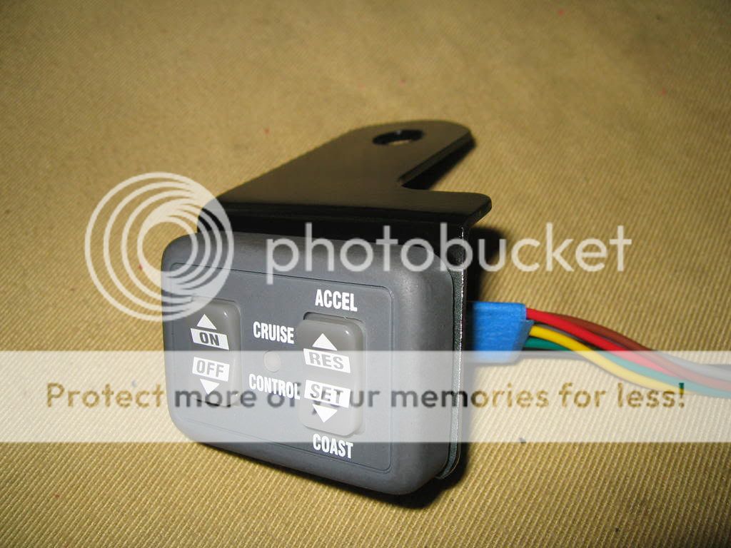
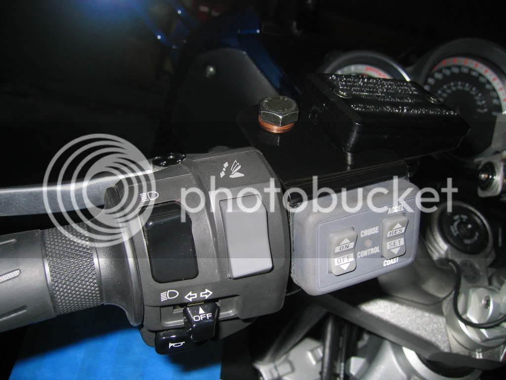
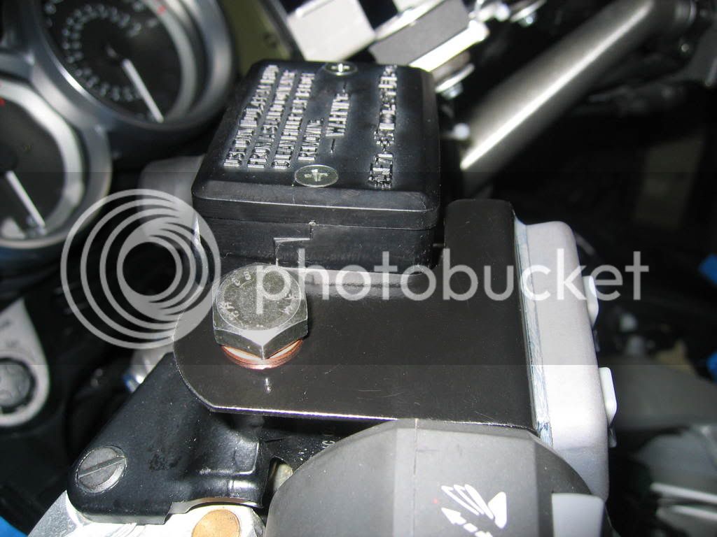
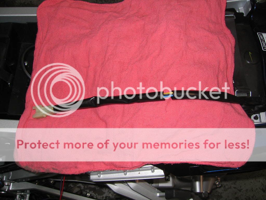
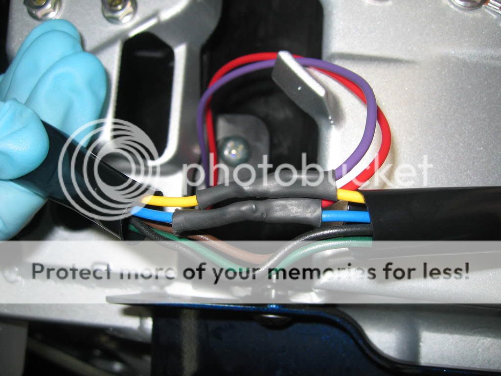
Control switch panel wiring and mount: Skyway’s mount looks very nice, but I decided to make one like Smitty’s. I put silicone sealer at the wiring opening first and then around the opening after it was secured to the bracket. The black and grey wires are for the back lighting of the panel, the grey wire was designed to tap into a light circuit so it would light up when lights are turned on. I tied it into the red wire which is the power feed, this will cause the panel lights to stay on at all times……no harm done and I didn’t have to cut into the factory wiring. The black wire simply gets grounded to a good ground source, I found a good place on the left side brake line bracket near the steering head. I used shrink tubing to insulate the entire harness before inserting the 4 pin terminals into the white connector.
Mount the switch panel assembly and follow factory wiring routing thru opening into front of engine compartment.
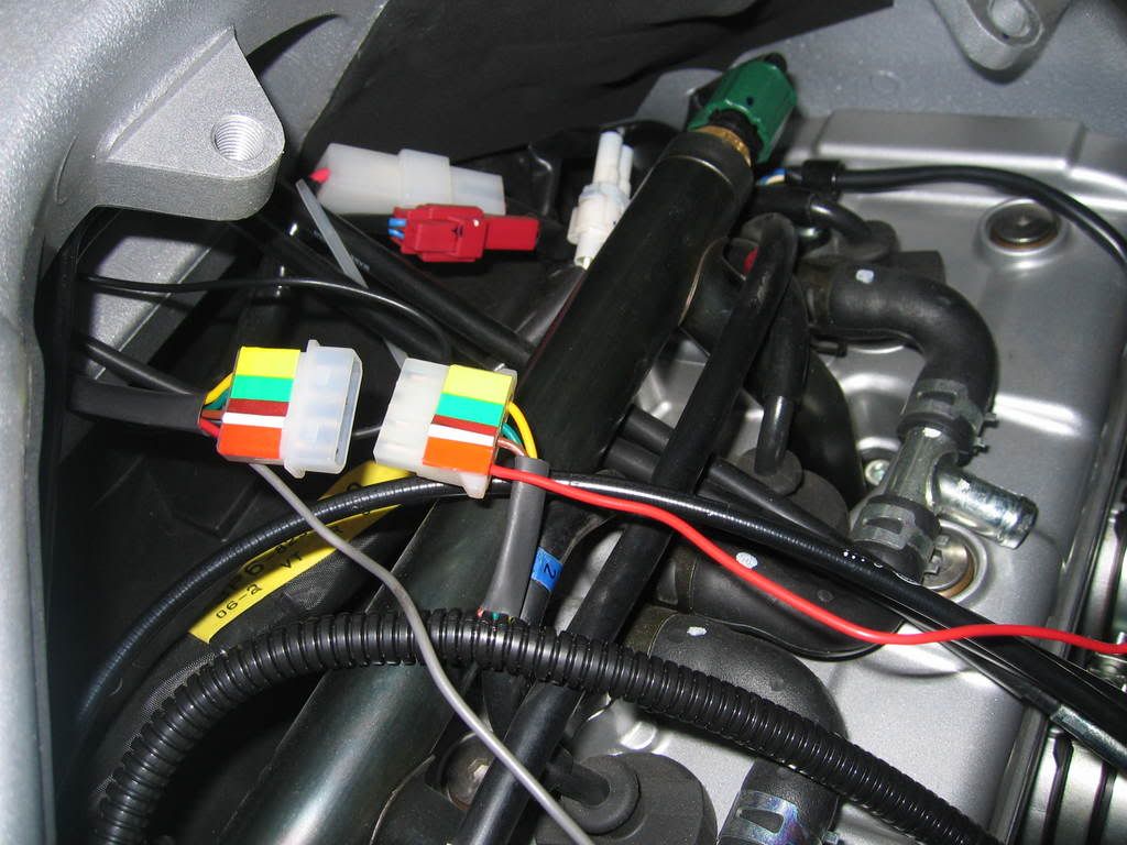
Route the green, yellow, brown, blue wires from the servo unit toward front of the bike following cable on the left side. Use wiring conduit to protect wires. The green, yellow and brown wires are cut to length and soldered back together, then the pin terminals are installed into the white connector matching colors to the control switch panel.
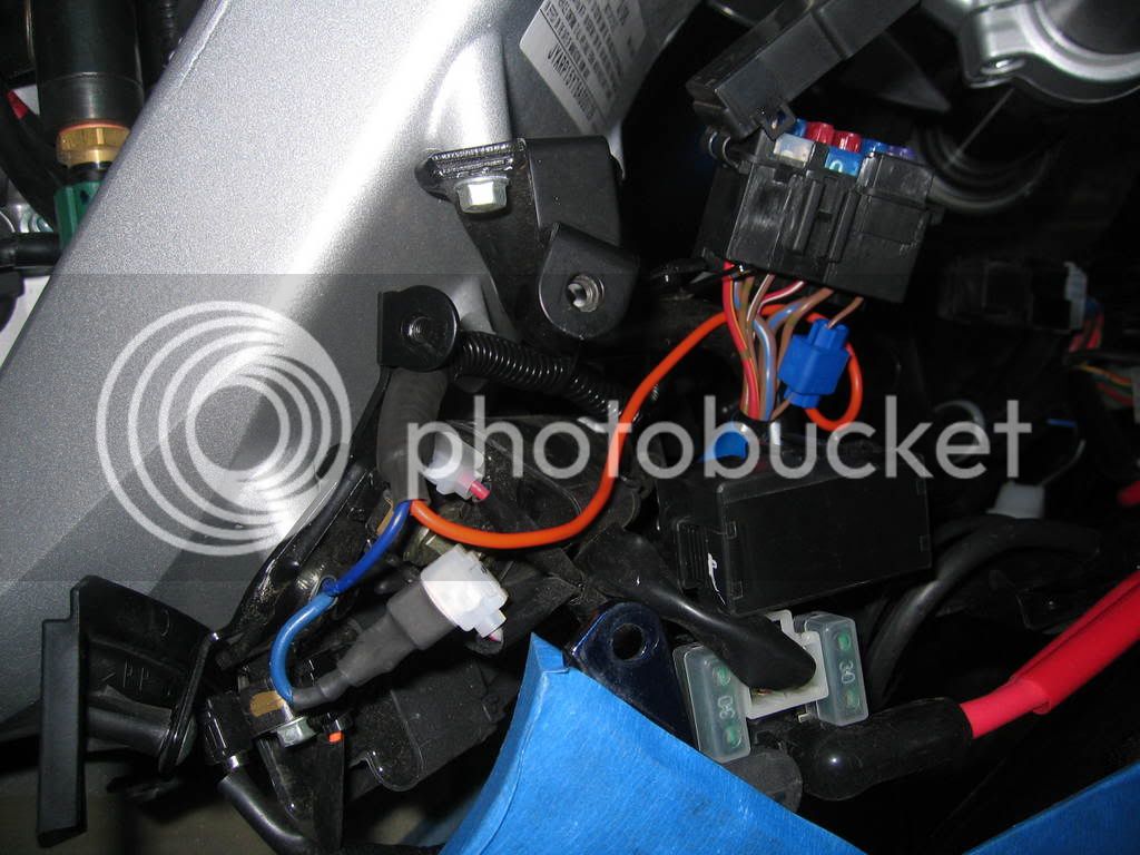
Power feed connection: The red wire that comes attached to the 4 pin connector with a 3 amp fuse and inline fuse holder is the power feed wire. I decided to do away with this fuse assembly and used the factory #12 fuse instead. This is for the 12 volt power adaptor located in the left compartment. I only use this for my GPS/PDA which draws very little currant so it should have no problems supporting the cruise unit as well.
I removed the fuse assembly from cruise unit, soldered a wire to length to reach #12 fuse and attached it with a scotch lock connector. This is the only scotch lock connector of the entire install. I had no choice because the length of the wiring exposed on #12 fuse was minimum. It would have been difficult to solder here. See picture.
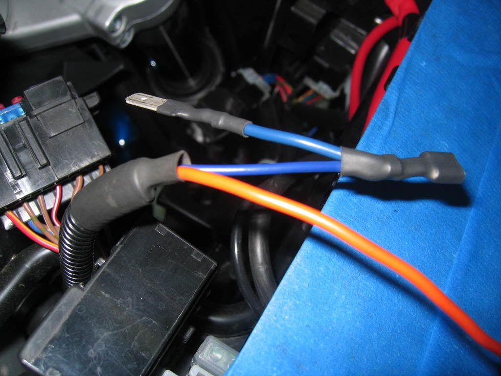
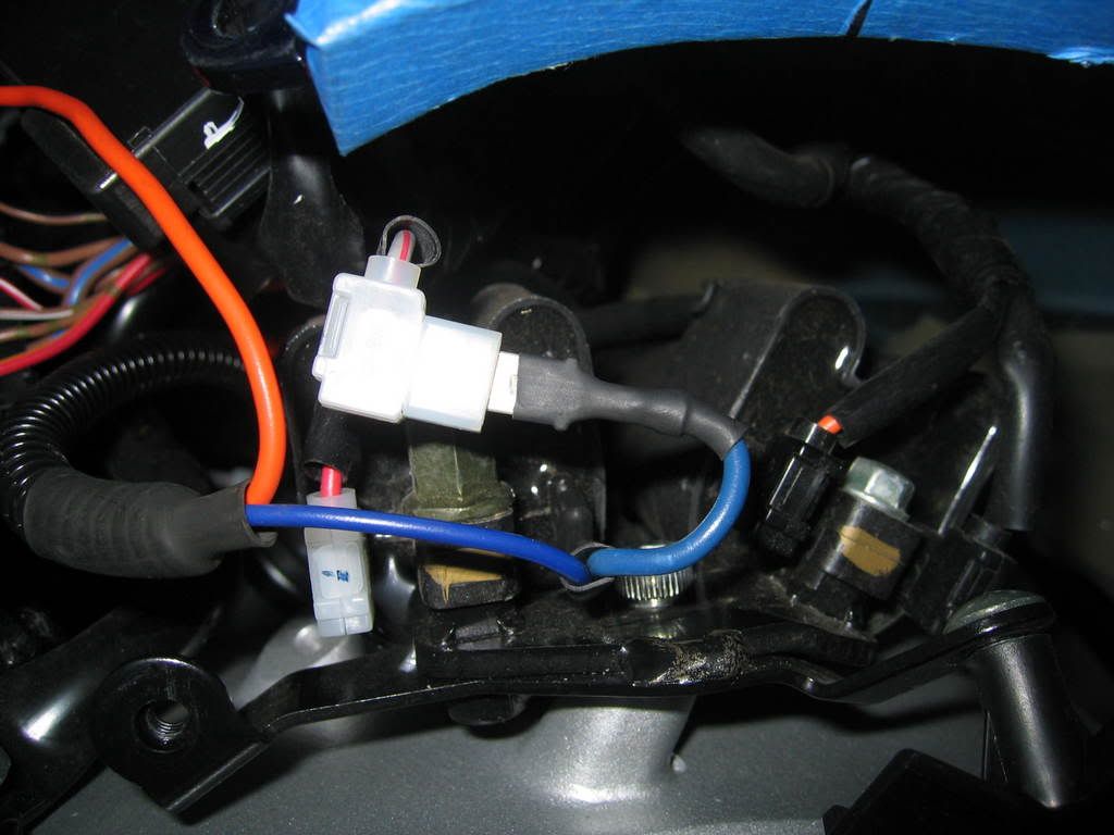
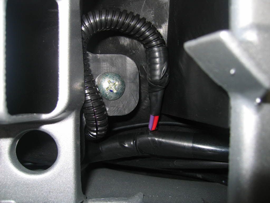
Tach signal: I didn’t want to cut into the ignition coil primary wire so I made an adaptor harness by soldering a female and a male terminals with shrink tubing insulation. I didn’t want to chance the bike running on two cylinders if this wire were to fail.
Reached maxinmum images allowed. Continue on next post.