Make sure you leave sufficient expansion volume in the tank...i.e...you do not want to totally fill the volume with liquid fuel as it will start to expand as it warms and overflow. Typically a fuel tank would have an unfillable vapor volume of 5 to 10% of total capacity. One way to do this is to make the fill bung extend into the tank so that a vapor volume will be created when the liguid reaches the bottom of the fill tube. Or, just make sure you never completely fill the tank but that approach is not idiot proof....LOL.
You are using an out of date browser. It may not display this or other websites correctly.
You should upgrade or use an alternative browser.
You should upgrade or use an alternative browser.
Auxiliary Cell Design
- Thread starter Joe2Lmaker
- Start date


Help Support Yamaha FJR Motorcycle Forum:
This site may earn a commission from merchant affiliate
links, including eBay, Amazon, and others.
Joe2Lmaker
Well-known member
Thanks.Make sure you leave sufficient expansion volume in the tank
That caution is noted. It's the reason Dean went with a filler neck on his design.
That's what I love about this forum. A place to learn from those more knowledgeable and willing to share their experience.
Joe2Lmaker
Well-known member
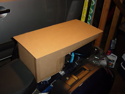
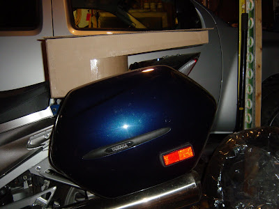
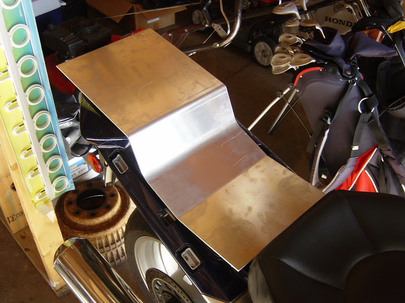
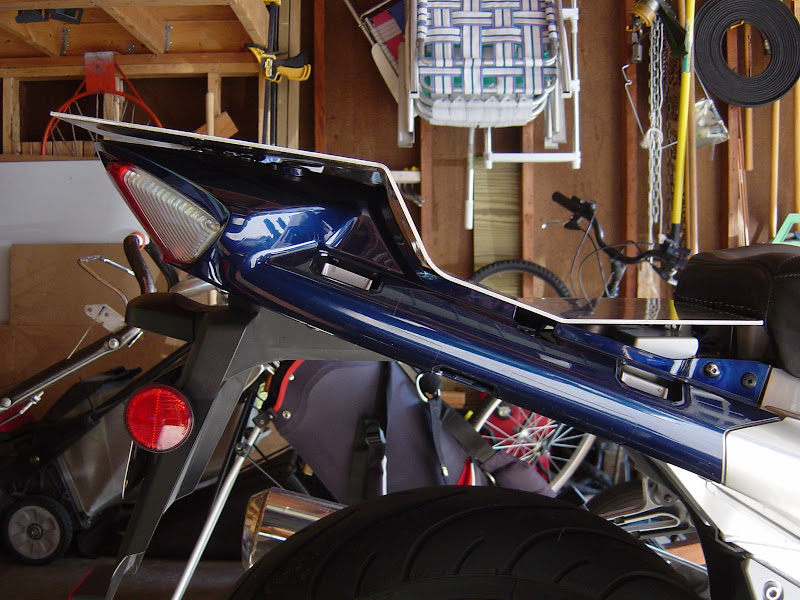
O.K. here it is, Revision 2. As always, I'm looking for opinions here.
Here are some shots of the CAD model I used to calculated the volume:
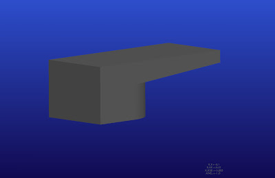
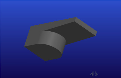
I thought it would be easier to see what the mock-up looks like without the top piece:
O.K. I see there is going to be a rev.3, but maybe by December I'll have a working tank! Of course road testing it is going to be a problem (snow).
Here are some shots of the CAD model I used to calculated the volume:
I thought it would be easier to see what the mock-up looks like without the top piece:
O.K. I see there is going to be a rev.3, but maybe by December I'll have a working tank! Of course road testing it is going to be a problem (snow).
Last edited by a moderator:
Checkswrecks
Well-known member
Pretty cool, but a couple of thoughts:
1. Fatigue is the enemy of sheetmetal. The fatigue crack in this design will form where the curved surface is welded to the flat surface. Try real hard to avoid welds in general and especially at right angles to a big flat surface like that. Suggestion #1: Make the top, front, two sides, and rear of one piece with gentle bends (CAD is a great resource to get the vertical corners right), then weld on the bottom. Suggestion #2: Make the entire Z-shaped bottom of a single piece. Give it a good half-inch or more of bend radius where your current sketch shows the bottom and top of the curved part.
2. Sheetmetal tanks are commonly held down by straps, because people long ago realized that cracks form at the edges of mounting tabs or where the wall thickness changes abruptly. Think carefully about how you'll hold the tank down. Also think about fatigue in terms of any tabs for light brackets, cargo tie-downs, etc.
3. Explosafe or any of the other foams are generally well-recognized as baffle material, but you'll need to check the IBA rulebook to make sure.
Hope this helps.
Bob
Joe2Lmaker
Well-known member
Checkswrecks, thanks. I've been thinking about your suggestions. I don't have the tools to build this tank out of sheetmetal. Believe me I wish I did. I would enjoy learning more about the sheet metal module of our CAD software. Plus, I think a well designed, steel tank could be lighter and stronger than a tank built out of aluminum plate.
Everyone, I've had a major set back and just when I thought I was out of the woods. Saturday after Thanksgiving I went to my favorite local aluminum and steel supplier. I was going to take photos of the materials I'm planning on using in this project. The plan was to reply to Checkswrecks and show how my design could actually be made extremely strong and have the added benefit of an internal baffle.
I went to the rack to take the photo, and the piece was gone! I thought it was a standard size 3/16" wall, round tube. I was wrong. I didn't realize when I went there in September and found the perfect piece that it was a drop (left-over) from a special order. I based my redesign on something they don't stock! I could have bought 3 feet of the stuff. I could have been cutting it up by now. Shit.
Here's a photo of what I can get today:
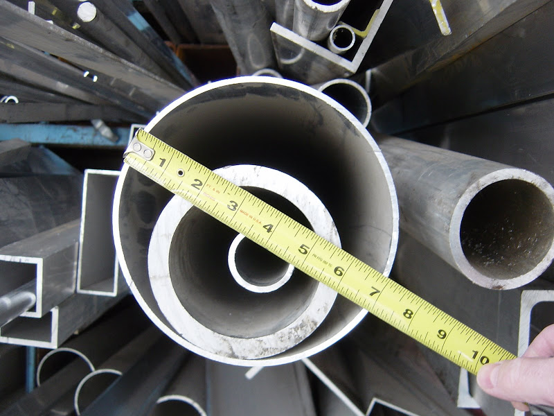
See where my thumb is? That's the diameter I was looking for. That was my solution to utilize the space under the passenger seat. The tube would make up part of what protrudes downward to fill that space.
Oh well, it’s a moot point now. I’ll have to come up with something else.
Everyone, I've had a major set back and just when I thought I was out of the woods. Saturday after Thanksgiving I went to my favorite local aluminum and steel supplier. I was going to take photos of the materials I'm planning on using in this project. The plan was to reply to Checkswrecks and show how my design could actually be made extremely strong and have the added benefit of an internal baffle.
I went to the rack to take the photo, and the piece was gone! I thought it was a standard size 3/16" wall, round tube. I was wrong. I didn't realize when I went there in September and found the perfect piece that it was a drop (left-over) from a special order. I based my redesign on something they don't stock! I could have bought 3 feet of the stuff. I could have been cutting it up by now. Shit.
Here's a photo of what I can get today:
See where my thumb is? That's the diameter I was looking for. That was my solution to utilize the space under the passenger seat. The tube would make up part of what protrudes downward to fill that space.
Oh well, it’s a moot point now. I’ll have to come up with something else.
Joe2Lmaker
Well-known member
I need a volunteer. I've begun fabricating.
I need someone who is still racking up miles during these long winter months.
This project has evolved into a two part solution. Part 1 is the mounting rack. Part 2 is the actual tank. I think I have a winning design for the bracket to hold the tank, and I bought materials today. The rear seat is removed and the bracket drops into place using the existing locators and lock.
I need a volunteer; someone with a GenII, already plumbed for an auxiliary tank.
The rack will be finished first, after that we could either mount something like a Jaz or RCi to the rack, or skip that and mount the wide, low, flat top custom tank.
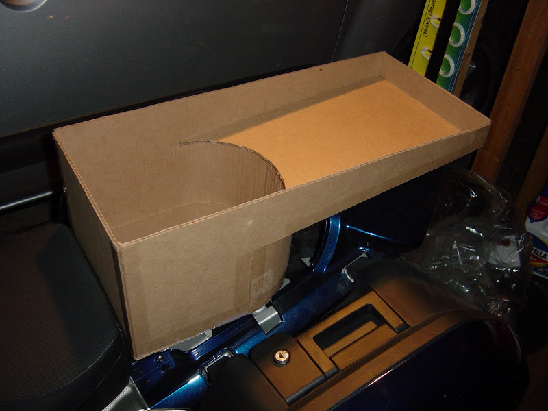
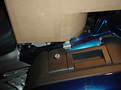
Sorry for the lack of photos. All of this has been worked out with paper and pencil drawings. I sort of accidentally stumbled on the design when I went to remove a box of parts that was sitting on the bike. The box was just sitting there in the space where the rear seat should be and I was slapped in the face by the obvious.
I need someone who is still racking up miles during these long winter months.
This project has evolved into a two part solution. Part 1 is the mounting rack. Part 2 is the actual tank. I think I have a winning design for the bracket to hold the tank, and I bought materials today. The rear seat is removed and the bracket drops into place using the existing locators and lock.
I need a volunteer; someone with a GenII, already plumbed for an auxiliary tank.
The rack will be finished first, after that we could either mount something like a Jaz or RCi to the rack, or skip that and mount the wide, low, flat top custom tank.
Sorry for the lack of photos. All of this has been worked out with paper and pencil drawings. I sort of accidentally stumbled on the design when I went to remove a box of parts that was sitting on the bike. The box was just sitting there in the space where the rear seat should be and I was slapped in the face by the obvious.
Checkswrecks
Well-known member
No apologies, Joe. I want to congratulate you on getting away from the CAD for this project. Being creative with sheetmetal's a fun art!Sorry for the lack of photos. All of this has been worked out with paper and pencil drawings. I sort of accidentally stumbled on the design when I went to remove a box of parts that was sitting on the bike. The box was just sitting there in the space where the rear seat should be and I was slapped in the face by the obvious.
Bob
Joe2Lmaker
Well-known member
It's hard to believe it's been a year since I started this project.
The train sort of left the tracks back in January.
Then it was Spring, time to ride again and the project went on the back burner.
Please excuse me for being presumptuous enough to think that anyone gives a shit about my progress on this project, but here it is...
This is a foam model cut to scale:
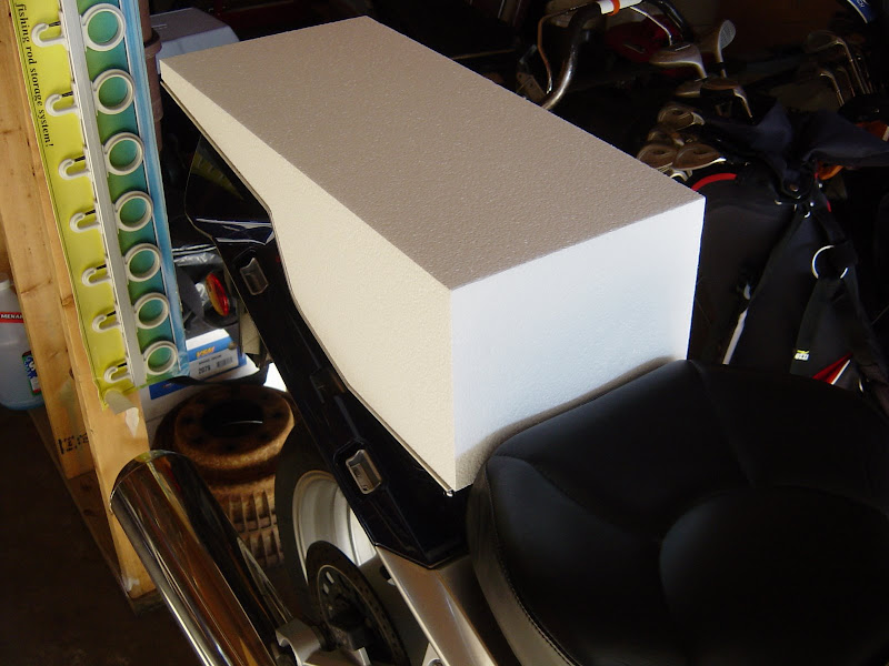
I had a bottom plate made so I could check the fits before committing to this design.
All of that led me to this:
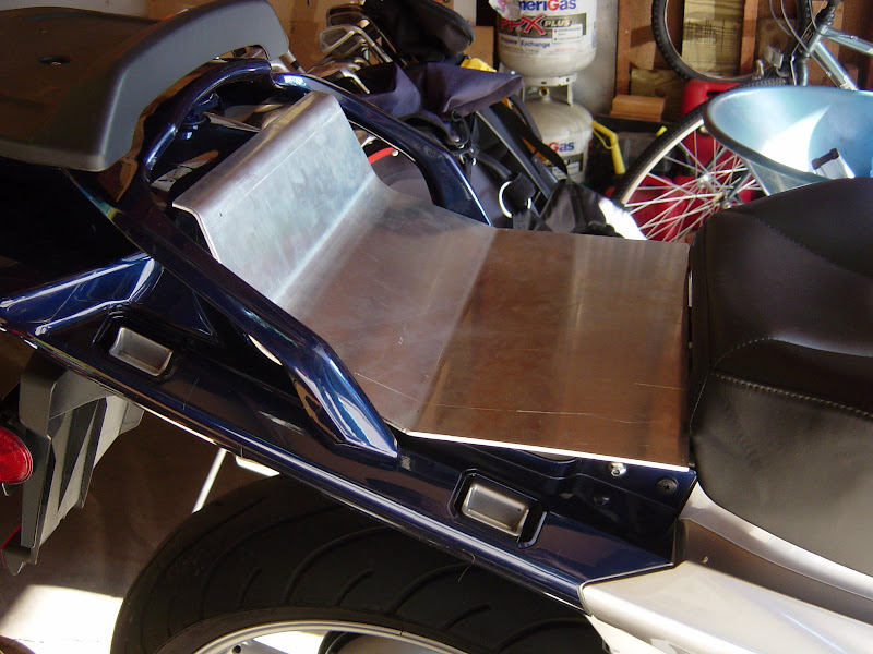
I really like the plate in the bottom photo. I'm leaning toward dropping the whole "over the tail" flat top idea. The smaller plate is wider and wouldn't be much taller than flat Tanji style tank would be.
The train sort of left the tracks back in January.
Then it was Spring, time to ride again and the project went on the back burner.
Please excuse me for being presumptuous enough to think that anyone gives a shit about my progress on this project, but here it is...
This is a foam model cut to scale:
I had a bottom plate made so I could check the fits before committing to this design.
All of that led me to this:
I really like the plate in the bottom photo. I'm leaning toward dropping the whole "over the tail" flat top idea. The smaller plate is wider and wouldn't be much taller than flat Tanji style tank would be.
dcarver
Well-known member
Dang, you have talent! Good progress, keep going!
taterides
Well-known member
I have been talking to a local custom tank fab shop. The design shown in picture 2 is similar to what we have discussed. For what little I know I like it best. The shop has also discussed curving the front of the tank to act as a back rest. Your progress looks great. Thanks.
Groo
The Endless Font of Useless Knowledge...
I am following your progress, and think you've got a wonderful design concept going. Look forward to future updates. At least it keeps me from looking at that "other" aux tank thread...Please excuse me for being presumptuous enough to think that anyone gives a shit about my progress on this project, but here it is...
Checkswrecks
Well-known member
Great to see you're back at it.
Since January? Shoot, I have a half-built airplane that I haven't touched since about a year ago!
Since January? Shoot, I have a half-built airplane that I haven't touched since about a year ago!
mdisher
formerly Renegade, get used to it.
Dude, that's awesome... I agree, there isn't any reason to go over the back/tail if you don't have too...All of that led me to this:
I really like the plate in the bottom photo. I'm leaning toward dropping the whole "over the tail" flat top idea. The smaller plate is wider and wouldn't be much taller than flat Tanji style tank would be.
Joe2Lmaker
Well-known member
I'm hoping some experienced LD guys are interested in this because I have a question.
I'm trying to establish Z=0. Or, how high does the bottom of a gravity feel tank need to be on an FJR?
In this photo: 1.)The bike is on its center stand 2.) The wheels are equidistant to the garage floor 3.) The bubble in the level is in the same position on the garage floor as it is shown in the photo 4.) The red line follows the line of the level
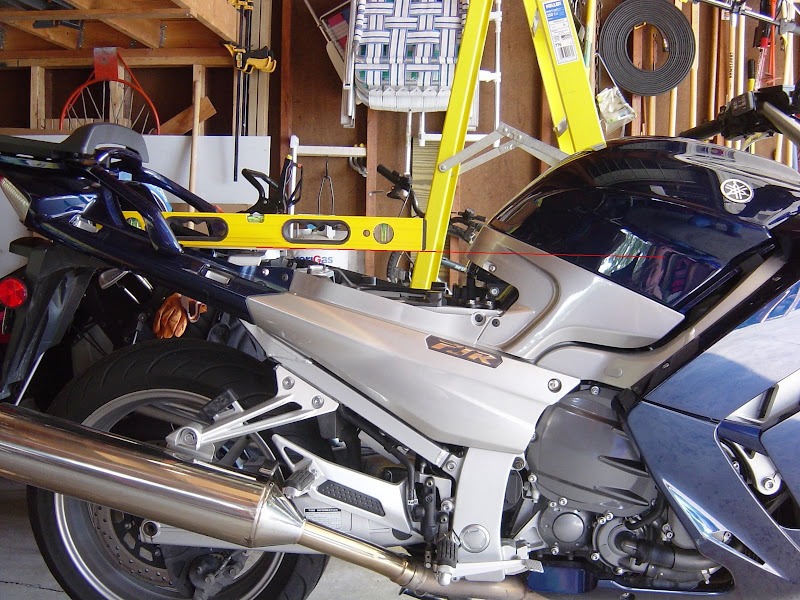
O.K. Here's the question: It looks to me that if the bottom of the auxiliary tank were at this level (my design puts it here) it would be high enough for a gravity feed system. I believe the bulkhead would be below the red line.
What do you guys think?
I'm trying to establish Z=0. Or, how high does the bottom of a gravity feel tank need to be on an FJR?
In this photo: 1.)The bike is on its center stand 2.) The wheels are equidistant to the garage floor 3.) The bubble in the level is in the same position on the garage floor as it is shown in the photo 4.) The red line follows the line of the level
O.K. Here's the question: It looks to me that if the bottom of the auxiliary tank were at this level (my design puts it here) it would be high enough for a gravity feed system. I believe the bulkhead would be below the red line.
What do you guys think?
Joe, you are correct - the bulkhead would be below the red line, and the difference in elevation would result in a gravity flow to the main tank. While your measurements are taken on the center stand it would seem to me that there is enough differential in your design to still have adequate flow with the bike on it's tires.
Looks good.
Looks good.
Capt. Bob
Bilge pump. A novel idea.
Where does the feed from the aux. tank enter the main?
Do you need to install another fitting into the main tank?
Curious.
Do you need to install another fitting into the main tank?
Curious.
Duff
Well-known member
I don't even want/need an AUX tank and this thread has my interest. :blink:
By all means... keep going! I like the direction it is headed!
By all means... keep going! I like the direction it is headed!
06 tank penetration - courtesy of Tom Melchild Clicky
Sampson prototype install - Clicky
Not hard to do - just a bit freaky to be drilling a hole in your main tank. Ain't no goin' back once you're there.
Sampson prototype install - Clicky
Not hard to do - just a bit freaky to be drilling a hole in your main tank. Ain't no goin' back once you're there.
Where does the feed from the aux. tank enter the main?Do you need to install another fitting into the main tank?
Curious.
Joe2Lmaker
Well-known member
A fitting needs to be added to the bottom of the tank. There's an excellent writeup here: Installing a Bulkhead Fitting on an FJR1300Where does the feed from the aux. tank enter the main?Do you need to install another fitting into the main tank?
Curious.
Also: smitty141's install on a 2005
GenII owners need to make sure they install it in the right location or it won't clear the heat shield. Read the last paragraph on this page: fjrmods
edit: I see kaitsdad answered your question before I could. I began writing this reply and got side track looking photos of his bulkhead fitting install.
Hey Hal,
Thanks for adding the link. I've been searching for half an hour and couldn't find it
Similar threads
- Replies
- 12
- Views
- 661