Guide to Removing the Air Induction System

Yamaha FJR Motorcycle Forum

Help Support Yamaha FJR Motorcycle Forum:

This site may earn a commission from merchant affiliate links, including eBay, Amazon, and others.
Is there any possibility the air being introduced into the exhaust is for the catalytic converters, has any body looked at those after the mod as been done?

If I remember WW I think took them out but was wondering if any body else has seen a difference.

The reason I ask is because I had an old piece of shit car I shared with a college roomate that had an air pump that ran off a v-belt on the engine and it was to get air to the catalytic converters.

 
Is there any possibility the air being introduced into the exhaust is for the catalytic converters, has any body looked at those after the mod as been done?
If I remember WW I think took them out but was wondering if any body else has seen a difference.

The reason I ask is because I had an old piece of shit car I shared with a college roomate that had an air pump that ran off a v-belt on the engine and it was to get air to the catalytic converters.
Lake Powell,

I still have my Kitties! Haven't got rid of them yet.

WW

 
Is there any possibility the air being introduced into the exhaust is for the catalytic converters
At idle the exhaust gases are in the right temperature range (1112F-1292F) that inducing oxygen into the mix burns the unburned exhaust gases. At higher temps, like during deceleration, you don't get burning you get booming, hence the backfiring. The induced oxygen then is a simple way to reduce emissions (at idle and cold running), except that for the end tinkerer it creates a maze of hoses and the backfiring.

Removing the system is going to pump more hydrocarbons through the cat, which mean more work for it. Exactly how that effects the cat's longevity remains to be seen, but Dale Walker has an interesting solution for that. :devil:

 
Dude!

I did this nearly exact procedure today. Had my PCIII to install, throttle spring mod to do and needed a TBS. I found the plugs at Lowes ($2.54), hose at AutoZone ($4.38).

I used the original length hose from the airbox, but fit the non-CA plug in the other end. Seemed easier to me that jacking with 1/2"ID hose on that fitting.

WW -- :clapping: Well done. I wish I had done this sooner.

Hello Everyone.
First lets get the disclaimer out of the way... This is the way I chose to remove my Air Induction System on my 07A FJR1300 and I figured I would share it with those of you looking for some guidance on this and/or haven't done it yet. I know there are plenty of ways to skin a cat. This is how I chose to do mine very cheaply. I am sure it can be done many other ways. This cost me less than $7 dollars to do.

Lets get started...

Hope this helps out,

Wicked Webby
 
Anybody know if the PAIR solenoid valve is triggered positive or sinked negative? Just wondering if there is some use for that extra electrical connector?
I'll have to check the schematics and see what they show.

:unsure:
True for both Gen I and Gen II.

When there is no voltage at the solenoid, the solenoid is open and passes air to the reed valves. Supplying 12 volts to the solenoid stops air flow to the reed valves (solenoid is closed). The solenoid is open when the ECU is running the cold enrichment map, then shuts off once the thermostat opens. The solenoid is also allowed to pass air when the engine is warm and below some RPM point (I know it is below 2k rpm but can't remember the exact number, I know it is very close to idle speed).

Since this connector gets switched on and off depending on conditions it would be a funky power source :lol:
Yes, yes... I was thinking from the first post down... "why not just unplug the electrical connector to disable the system??". This would not provide the cleaner head, but it would keep the service boogey man away.

But as usual, my man Alan has dispelled the myths --> the solenoid is Normally Open. So, the choice would still be to plug just the inlet from the airbox or remove the whole thing, as WW did. Nice job, BTW!!

-BD

 
So the fresh air from the airbox does not ventilate the crankcase through the valve cover? Just direct from induction into exhaust port?

 
So the fresh air from the airbox does not ventilate the crankcase through the valve cover? Just direct from induction into exhaust port?
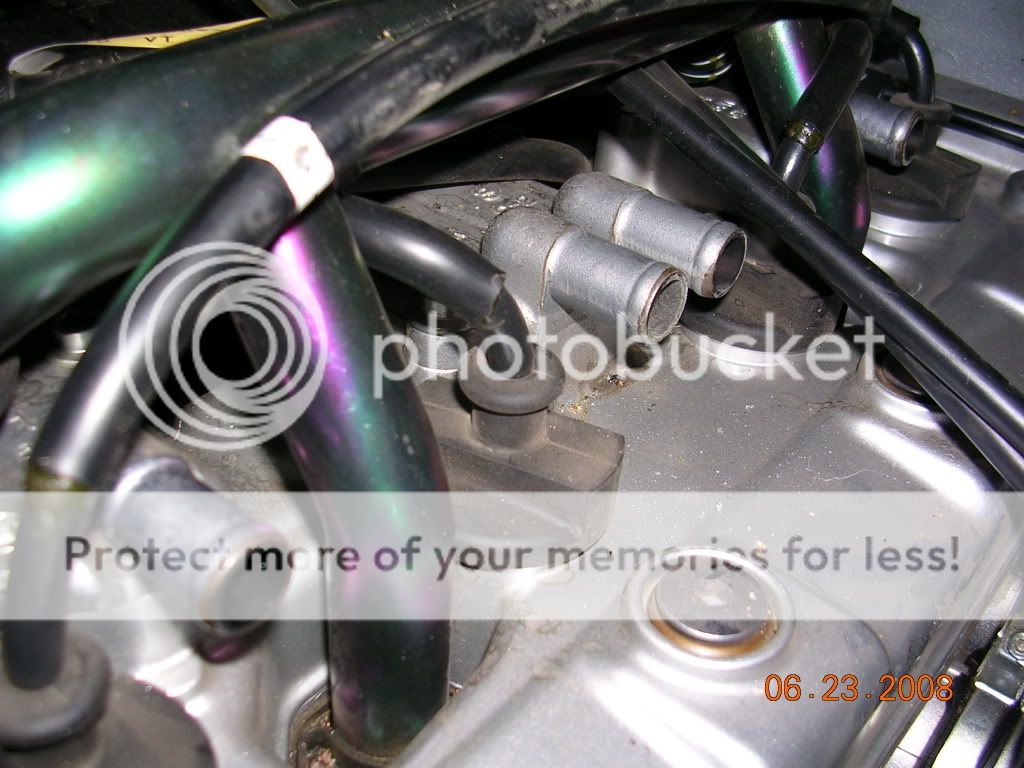
There is a nice picture on pg 7-11 of the shop manual (I pilfered the above response from 7-15), the air is ducted onto the exhaust valve.

 
So the fresh air from the airbox does not ventilate the crankcase through the valve cover? Just direct from induction into exhaust port?
Borrowing Webby's picture:

SmogRemoval7.jpg


The four open tubes go directly to the reed valves, right under the valve cover. When the reed receives negative pressure it opens and air goes down through a passage hole in the cylinder head to the exhaust runner in the cylinder head, just above the maximum valve lift area. Air is inducted well before the outlet header flange.

 
Last edited by a moderator:
FYI,

I drilled the right side center of the box, to allow for some right side air intake.

I drilled dozens of holes with a small drill bit, which turned the panel into a screen that looks like a kitchen strainer.

(will keep out leafage, bugs and debris) (2.5mm bit?) (maybe 50% of plastic remaining?)

After rechecking the TBS, it didn't change at all. C1-C3 were "money" and C4 was just a wisker low, well within spec.

I barely breathed on the scew to make them all perfect. I've done sync's before where perfect was not even in the cards.

So, at idle, I'm saying zero affect on intake balance.

What's happening at full throttle may be a different story. I assume that is when she will be looking for more air.

I can definitely hear new sucking sounds.....

I wander if the shoehorn on the left side, which reaches into the filter should be trimmed some.

I assume that it is there to help balance the flow across the cylinders.

With new fresh air by C4, maybe that shoehorn should get 25% smaller?

Filter access sure would get much easier.

Anyone else think that filter cover can be a pain in the ass to remove and replace?

Summary:

I think I found that much more modest mods, do give much more modest results.

(not always the case in man's search for power)

WW reported that his radical mod demanded significant throttle syncing.

Where, my adding just a couple extra sq. inches of opening required none.

I think this means the added opening had no impact at idle and probably little impact under throttle.

Oh well. It was free.

 
FYI,
I drilled the right side center of the box, to allow for some right side air intake.

I drilled dozens of holes with a small drill bit, which turned the panel into a screen that looks like a kitchen strainer.

(will keep out leafage, bugs and debris) (2.5mm bit?) (maybe 50% of plastic remaining?)

After rechecking the TBS, it didn't change at all. C1-C3 were "money" and C4 was just a wisker low, well within spec.

I barely breathed on the scew to make them all perfect. I've done sync's before where perfect was not even in the cards.

So, at idle, I'm saying zero affect on intake balance.

What's happening at full throttle may be a different story. I assume that is when she will be looking for more air.

I can definitely hear new sucking sounds.....

I wander if the shoehorn on the left side, which reaches into the filter should be trimmed some.

I assume that it is there to help balance the flow across the cylinders.

With new fresh air by C4, maybe that shoehorn should get 25% smaller?

Filter access sure would get much easier.

Anyone else think that filter cover can be a pain in the ass to remove and replace?

Summary:

I think I found that much more modest mods, do give much more modest results.

(not always the case in man's search for power)

WW reported that his radical mod demanded significant throttle syncing.

Where, my adding just a couple extra sq. inches of opening required none.

I think this means the added opening had no impact at idle and probably little impact under throttle.

Oh well. It was free.
I think you want a different thread, maybe one on airbox mods? WW just can't seem to leave air alone.

 
Maybe this has been treated, I didn't see it-but eliminating/bypassing the airbox also takes the temp sensor out of the equation-the temp sensor (located in the airbox) adjusts fuel flow depending on temp (obviously). Because I run nitrous, I have to hit the temp sensor because the nitrous temperature tricks the sensor into adding more fuel.

I'm wondering if the Webby set-up may have any repercussions re the temp sensor being eliminated-if not it is a very trick job.

 
Nobody's talking about bypassing the airbox. Nobody's even talking about the intake or combustion process.

The discussion is the air injection system, an emmissions device that feeds atmospheric air into the exhaust ports under certain conditions, giving enough oxygen to burn any remaining hydrocarbons in the exhaust stream.

The discussion of airbox is about the hose that supplies air to this system. The system can be disabled by blocking that hose, but all the ugly plumbing is still there on top of the motor, and in the way. What folks are doing is removing all the hoses to clean up the top of the motor, and then they have to block the four individual ports on the cylinder head.

(Post #50 is apparently in the wrong thread; WW had a thread about modifying the airbox for increased flow.)

 
Last edited by a moderator:
OOPS. Shows you what I know-or, don't! Although, I do see a hose clipped off from the airbox?

 
Last edited by a moderator:
OOPS. Shows you what I know-or, don't! Although, I do see a hose clipped off from the airbox?
Correct, that is the hose that supplies the fresh air to complete the combustion process. BTW, this isn't exactly the first time this has been done.

 
A Dorman Products Bypass Cap assortment part #02253 found at Advance Auto Parts as part #9110054 contains caps that will work for this mod. I needed two boxes to obtain enough caps and each box cost me $3.48.

I used the 1/2" ID caps for the four valve cover tubes and yes, they are a tight fit. A 5/8" ID cap works very well for the one air box tube. No clamps were needed.

Alternatively, I suppose you could buy the plugs individually, eliminating the need to buy two boxes, butt I could not find them individually locally. Dorman's web site below shows different part numbers for each size as well as the assortment.

https://tinyurl.com/68f67o

 
Another positive side benefit of this procedure is reduction in head pipe temps. This is the main attraction of this mod for the cruiser crowd because it keeps their chrome pipes from turning blue/brown/gold.

It certainly can't hurt to reduce temps anywhere on an FJR AFAIC.

 
A Dorman Products Bypass Cap assortment part #02253 found at Advance Auto Parts as part #9110054 contains caps that will work for this mod. I needed two boxes to obtain enough caps and each box cost me $3.48.
I used the 1/2" ID caps for the four valve cover tubes and yes, they are a tight fit. A 5/8" ID cap works very well for the one air box tube. No clamps were needed.

Alternatively, I suppose you could buy the plugs individually, eliminating the need to buy two boxes, butt I could not find them individually locally. Dorman's web site below shows different part numbers for each size as well as the assortment.

https://tinyurl.com/68f67o

I used the 5/8" bypass caps throughout. Just used hose clamps on the valve cover inlets, and the stock compression clamp on the airbox. Clean. After the TB sync, I also took the opportunity to replace the stock TB vacuum plugs with some longer 1/8" caps. The OEM are so short, kinda hard to grab the little buggers.

 
Last edited by a moderator:
As luck would have it I am going to both the hardware store and autozone today...

I am lifting the tank this week as well.

This is something I will do... Perfect timing !!

Thanks WW

 
Top