AVCC power on/off logic

Yamaha FJR Motorcycle Forum

Help Support Yamaha FJR Motorcycle Forum:

This site may earn a commission from merchant affiliate links, including eBay, Amazon, and others.

dbx

Well-known member
FJR Supporter
Joined
Jan 22, 2006
Messages
426
Reaction score
9
Location
Biloxi, MS - USA
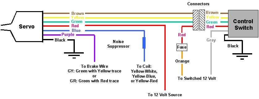
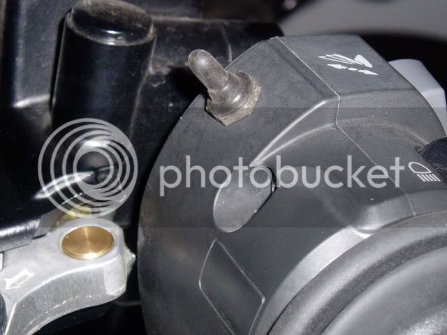
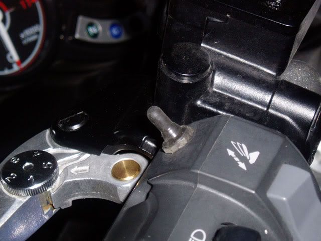
Anyone know what the Power on/off signals look like between the control panel and the servo? When I looked at the AVCC manual and saw that the green wire was labeled "Set" and the yellow wire labeled "Resume", I assumed that putting +12VDC on either of those wires would trigger the corresponding function, and it worked perfectly, so simulating Set and Resume with a small toggle switch was easy. (See pics below for my single SPDT w.center OFF toggle switch, which replaces the entire control panel.)

Pushing the switch in one direction connects brown (+12VDC) to green (Set). Pushing the switch in the other direction connects brown (+12VDC) to yellow (Resume). Release the switch and it returns to the center OFF position.

But how would I simulate a 'Power Off" signal to the servo? Bring both green and yellow high momentarily? If so, is that a toggle, where bringing both wires high a second time would toggle the system back on again?

avcc1.jpg


avcc2.jpg


dbx

 
Just put an on/off toggle switch or whatever in the brown +12V circuit into the servo. The little control panel has a latching circuit on the brown power circuit. When you press 'On' the circuit latches on and stays on until you press 'Off' or until the power is cut off with the ignition switch.

It's optional anyway if you switch the brown wire. I didn't use the control panel. The brown wire is fed from a maintained switch in my system. I never turn it off.

 
As stated before, the brown wire stays ay 12 volts when the unit is turned on, and drops when the unit is turned off. the keypad measured with my cheap-ass ohmeter with a half dead battery shows a connection between red and brown when the on button is pressed. Something in the control unit latches when it sees this, and the brown wire stays hot even after the on button is released. I see a resistance between the red and brown wires when the off button is pressed, but I can't even guess with my damn meter right now. Apparently the latch is broken by that resistor on the brown wire, turning the servo off.

Unless you HAVE to have an off button, applying and leaving keyed 12 volts on the brown wire will have the unit on when when the bike is on, and your switch as you have it will apply set/coast one way and resume/accel the other, and has been done before. It will disengage with the brake light, or by clutching (sudden engine race disengages, and actually rather quickly, before you could even call it a racing engine.)

BTW, the system does tap-up and tap-down, too.

 
Last edited by a moderator:
As stated before, the brown wire stays ay 12 volts when the unit is turned on, and drops when the unit is turned off. the keypad measured with my cheap-ass ohmeter with a half dead battery shows a connection between red and brown when the on button is pressed. Something in the control unit latches when it sees this, and the brown wire stays hot even after the on button is released. I see a resistance between the red and brown wires when the off button is pressed, but I can't even guess with my damn meter right now. Apparently the latch is broken by that resistor on the brown wire, turning the servo off.
Unless you HAVE to have an off button, applying and leaving keyed 12 volts on the brown wire will have the unit on when when the bike is on, and your switch as you have it will apply set/coast one way and resume/accel the other, and has been done before. It will disengage with the brake light, or by clutching (sudden engine race disengages, and actually rather quickly, before you could even call it a racing engine.)

BTW, the system does tap-up and tap-down, too.
Wow.. I'm glad I came across this thread, as I just bought a AVCC today for an install tomorrow. I would MUCH rather have this switch setup instead of the control box. Could someone point me in the right direction for a schematic to go sans control box? I've seen the install instructions on both this site and on fjr1300.info.com.

Jason

 
Wow.. I'm glad I came across this thread, as I just bought a AVCC today for an install tomorrow. I would MUCH rather have this switch setup instead of the control box. Could someone point me in the right direction for a schematic to go sans control box? I've seen the install instructions on both this site and on fjr1300.info.com.
Jason
One of the simpler schematics I found is this one:

wiring.jpg


which I stole from here:

Audiovox Install

Just replace the control panel with a single toggle switch: Single Pole Double Throw (SPDT), spring-loaded momentary contact, center off. Remove the Red (fused Orange) wire from the connector, it's no longer used. That leaves you with just the Brown, Yellow, and Green wires. Connect Brown to the switch's center post, then connect the two remaining wires to the other two switch terminals. I oriented my switch so that pushing the toggle 'up' meant Resume/Accel, while pushing the switch 'down' meant Set/Coast. It seemed more intuitive that way.

If I really had to, I might be able to dig up a source for the switch I used, which came from DigiKey. It's smaller than anything I was able to find locally. So small, in fact, that three of them would fit where I put mine.

dbx
Thanks! This should be a huge help. I've just spent the last hour reading the horror stories on the GEN II installs.. however, they seem to be solved with the #7 switch to off. Tomorrow should be an interesting day, provided I can find a similar switch from Radio Shack.

 
As stated before, the brown wire stays ay 12 volts when the unit is turned on, and drops when the unit is turned off. the keypad measured with my cheap-ass ohmeter with a half dead battery shows a connection between red and brown when the on button is pressed. Something in the control unit latches when it sees this, and the brown wire stays hot even after the on button is released. I see a resistance between the red and brown wires when the off button is pressed, but I can't even guess with my damn meter right now. Apparently the latch is broken by that resistor on the brown wire, turning the servo off.
Unless you HAVE to have an off button, applying and leaving keyed 12 volts on the brown wire will have the unit on when when the bike is on, and your switch as you have it will apply set/coast one way and resume/accel the other, and has been done before. It will disengage with the brake light, or by clutching (sudden engine race disengages, and actually rather quickly, before you could even call it a racing engine.)

BTW, the system does tap-up and tap-down, too.
Thanks, guys. I thought there might be a little more magic to it than that, but that's exactly how I wired mine up. No on/off switch, so it comes on when the bike is on and turns off when the bike is off. I didn't realize the control unit was simply latching the brown wire at +12VDC. Simple enough.

dbx

 
I am not trying to say that you stole my idea and forgot to pay my royalty. :rolleyes:

I am however, showing you what you may be looking for. :clapping:

The Original AVCC Switch Thread

Switch models included! Oh, and BTW, a ON/OFF switch is HIGHLY recommended. Accidentally hitting the switch will resume the bike when you least want it to! :eek:

-BD

 
Last edited by a moderator:
Oh, and BTW, a ON/OFF switch is HIGHLY recommended. Accidentally hitting the switch will resume the bike when you least want it to! :eek:
-BD

Yah, that's what's always concerned me about using a toggle and bypassing the on/off function. It's not like I never inadvertently 'bump' a switch or something - and like you say, hitting the 'resume' function at the wrong time could be rather exciting ?

 
I am not trying to say that you stole my idea and forgot to pay my royalty. :rolleyes:
I am however, showing you what you may be looking for. :clapping:

The Original AVCC Switch Thread

Switch models included! Oh, and BTW, a ON/OFF switch is HIGHLY recommended. Accidentally hitting the switch will resume the bike when you least want it to! :eek:

-BD
Thanks BrunDog.. you made me glad I got my tank off today, took a look at everything, and decided this was a project best left for another day. I did however, order the switches, which will allow me some more time for research. It seems people are making this install seem harder than it needs to be..until you physically look at the task at hand. Suppose I'll keep reading.

 
Top