RaYzerman19
Go Wings!
FSM says 47 ft. lbs. for the crank rotor bolt....... seems like a lot.... wait to final torque it after the engine is all back together, spark plugs in. You might get close. Be happy if it's close.


Answered above1. Ray - in your post #11 - is it your understanding that the orientation of the cam lobes pictured is what the #1 cylinder should look like. IOW - the view of that drawing is looking at the motor from the left turn signal side? If that is true, then the #4 cam lobes would be facing inward toward each other (as in Fred's picture).
Answered above2. Woofooshee - I'm still trying to understand the "lead" the cams part? If I understood you in post #16, by "forward" side, you mean the side of the chain that is closest to the exhaust header? Keep that side tight when installing the exhaust cam. Then keep the chain between the cams tight as we install the instake cam. Have a got that correct? I'm also thinking that I will zip tie the crank at TDC, then zip tie the exhaust cam after it is installed, then zip tie the intake cam after it is installed, then (and only then) release the cam chain.
Answered above3. In the same drawing shown by Woofooshee in post #16, there are cam lobes drawn in hidden lines behind the cam gears. Are those the cam lobes for cylinder #1 (I'm just backing up question #1 in this post)?
a refers to the holes in the #4 lobe closest to the sprocket. Those holes are straight up on a correctly timed cam when #1 is at TDC on compression, and line up with the arrow on that cap nearby..4. Also in the same drawing, on both cam gears, there appears to be some small notches or marks identified by an "A". May I assume that the orientation of the "A" marks ensures that we don't get the cam gears 180 degrees out of sync?
The E is for "Exhaust." The holes by the stamped 'E' are where the bolts go through the sprocket to attach to the exhaust cam. those holes are empty on the sprocket attached to the intake cam.5. Trivial question - what does the "E" mean that is stamped on both cam gears?
I'm pretty sure one of the cams has valves opening on one of the cylinders 2 or 3, and the other one has the other cylinder with some valves partly open.6. Can anyone confirm that when the crank and both camshafts are oriented correctly for timing purposes, that at this instant, there are NO valves open (partially or fully)? IOW - are all of the lobes off the buckets? I think this is important. The reason we had trouble in the first place was because we were trying to over come the valve spring(s) to set the camshafts down. This very little amount left no slack in the chain to work. We were able to use the bolts (4 of them) on the cam bearing/block (the one with the lateral camshaft guide built in it) to overcome the valve spring. But it would seem to me that it would be a whole lot easier to set the time if we didn't have to fight a valve spring. If one (or more) of the valves is open (or partially open) when the cams are in time with the crank, can anybody indicate which (and by how much)?
Answered, but I'll add that my term "leading" and his term "skipping a tooth" are the same thing. It's impossible to install the cams with the marks lined up and the chain tight. You either back the crankshaft a few degrees to give the chain enough slack to get the cams in, or you install the cams a tooth ahead of where they belong so that when the tensioner comes down on the chain, they'll back into the correct position.7. Bob - in your post #25, you indicate that you learned a trick by "skipping a tooth". Can you elaborate on this, please?
First, not sure why that bolt would have been pulled. No reason for it just for the cams.8. Finally, thinking positively that we can in fact DO THIS, can anyone provide the torque spec for the crank rotor bolt? There was no lock tight on that bolt, but should we use some and if so, which kind (blue or red). Anybody have a problem with my previously proposed method of torqueing this bolt (bike on the ground in 5th gear, front wheel against a wall, rider sitting on the bike stomping on the rear brake)? Of course the compression of the pistons won't provide enough resistance for me to torque this bolt. If I meet a stop on a stroke, then we know there are much bigger problems than torqueing that bolt. I could use my impact wrench and hunk down on it, but the last thing I need now is a stripped or sheared bolt in a crankshaft. LOL.


I just did my first valve check and set the cams aside only. I only removed the cams when #1 was at TDC and the alignment holes were aligned with the arrows on the #3 camshaft caps. I never spun the motor unless the cams shafts were back in place and the alignment holes lined back up with the #3 camshaft cap marks. If you remove the cams and then spin the motor, then you have a whole new alignment issue.Out of all this comes some positive learning from a negative experience........ one knows what to do next time or on your first valve check/shim change. While checking your valves, you're spinning the engine, taking your readings, or perhaps taking a second set of readings. If you are going to change shims, it is best to spin your engine to leave #1 at TDC, crank and cam timing marks aligned, cam chain tie-wrapped at crank and at sprockets, loosen CCT, proceed with shim changes. With the cams back in, it is then easy to verify the timing marks are all still OK at a glance.
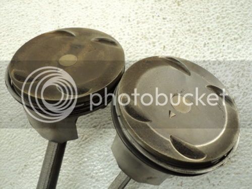
Not much. Those dimples do not clear the valves if the valve is actually open from a mistimed cam (i.e. cam chain skipped some teeth.)Yes, ^^^^^ but these dimples can help a lot in a mistake ''by hand,ratchet'' to protect the valves because the slope that they have i believe..
Wait! A valve clearance check is done with the cams INSTALLED. Why would you set them aside?I just did my first valve check and set the cams aside only. I only removed the cams when #1 was at TDC and the alignment holes were aligned with the arrows on the #3 camshaft caps. I never spun the motor unless the cams shafts were back in place and the alignment holes lined back up with the #3 camshaft cap marks. If you remove the cams and then spin the motor, then you have a whole new alignment issue.Out of all this comes some positive learning from a negative experience........ one knows what to do next time or on your first valve check/shim change. While checking your valves, you're spinning the engine, taking your readings, or perhaps taking a second set of readings. If you are going to change shims, it is best to spin your engine to leave #1 at TDC, crank and cam timing marks aligned, cam chain tie-wrapped at crank and at sprockets, loosen CCT, proceed with shim changes. With the cams back in, it is then easy to verify the timing marks are all still OK at a glance.
Agree if the engine runs!But if you turn the engine by your hand and if there something is out of alignment,these dimples can help to absorb some force from the pistons to the edge of the valves..My opinion.Not much. Those dimples do not clear the valves if the valve is actually open from a mistimed cam (i.e. cam chain skipped some teeth.)Yes, ^^^^^ but these dimples can help a lot in a mistake ''by hand,ratchet'' to protect the valves because the slope that they have i believe..

Enter your email address to join: