


garyahouse
newbs need the forum
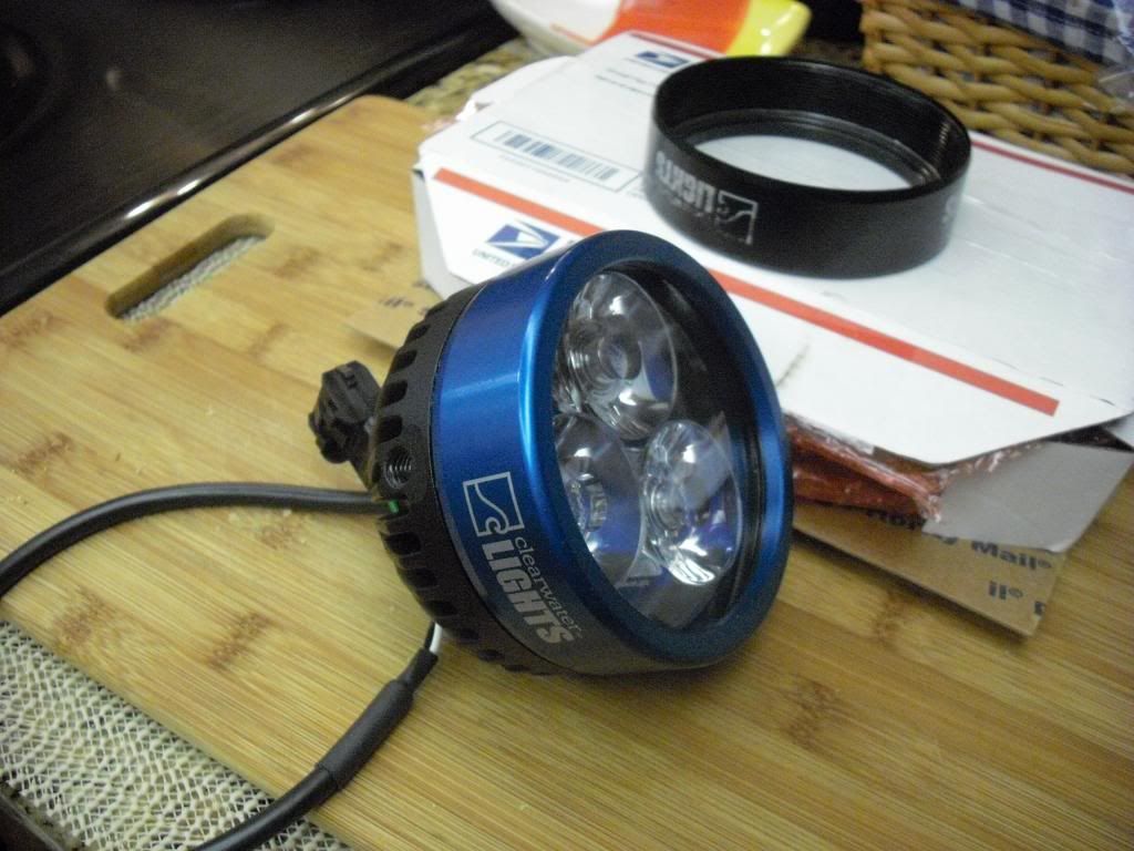
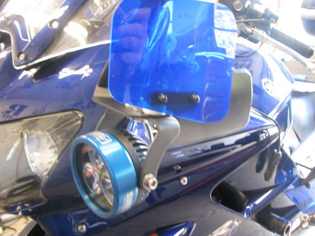
It all began with changing out the bezels for the 25.00 upgrade to blue. They come in black (below)
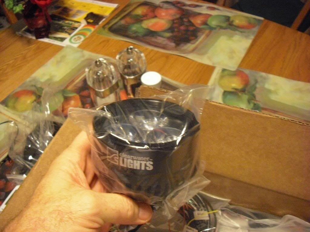
Getting them off was a challenge as the factory puts them on pretty snug. I used a vise... and an oil filter wrench. I wrapped the lens with a couple layers of masking tape to prevent damage. However, I learned that the white logos come off when using this method. Look closely at the black bezel. Notice that part of the Clearwater logos came off. Good thing I don't need to keep these black bezels. Do yourself a favor and have 'em done at the factory before you order them. I simply hand tightened the blue bezels.
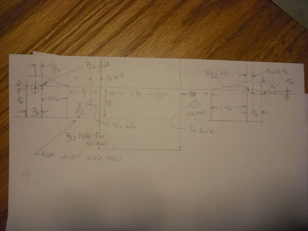
I didn't like the factory supplied "box" supplied for the dimmer control. So I decided to fab up my own. I started with doing a little measuring, then i drew it out on a piece of card stock paper:
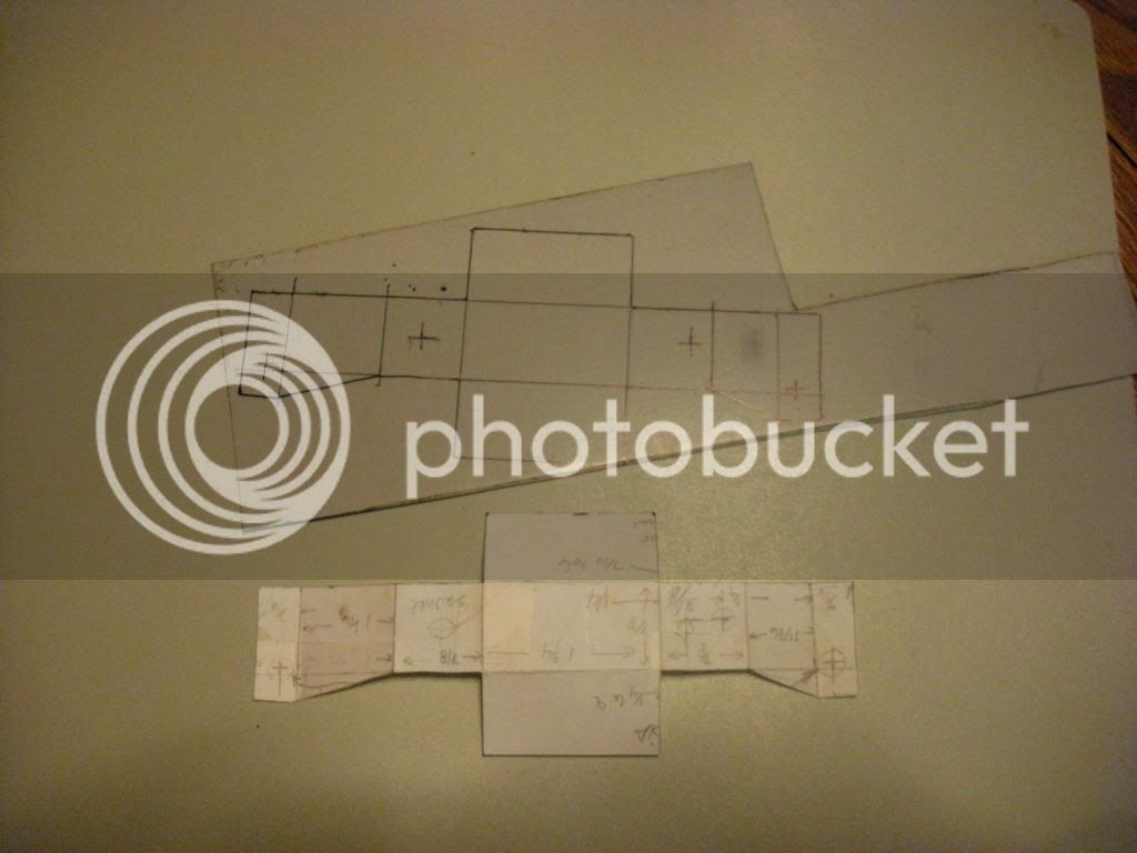
I cut it out and then traced it onto a piece of sheet metal:
First i drilled the holes. You'll notice that the front and back are off center a little. This is to accommodate the shape and location of Clearwater's switch...
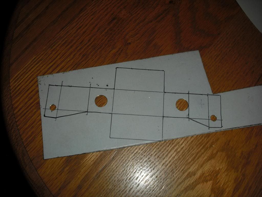
One of the two larger holes (the one on the left) was supposed to be a lot smaller, but a decent sized washer cured the problem later on.
Anyway, next, I cut it out and filed the edges:
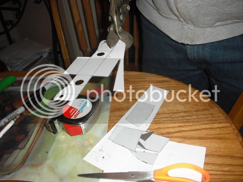
Then it was time to do some bending. I wanted to make it so that the flange was located on the bottom, with the hole slightly off to the side so that it would fit right where i wanted it to go... If I had it to do again, I would have made it about 1/4 inch shorter. Oh well.
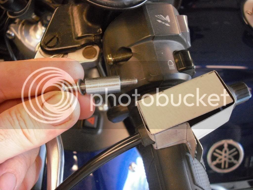
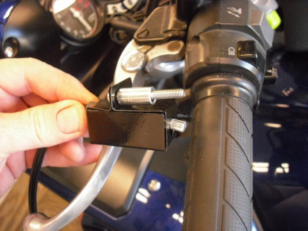
Below, right next to my finger you can see the factory screw ready to be replaced by a longer stainless cap screw and an appropriate sized sleeve (available at any hardware store):
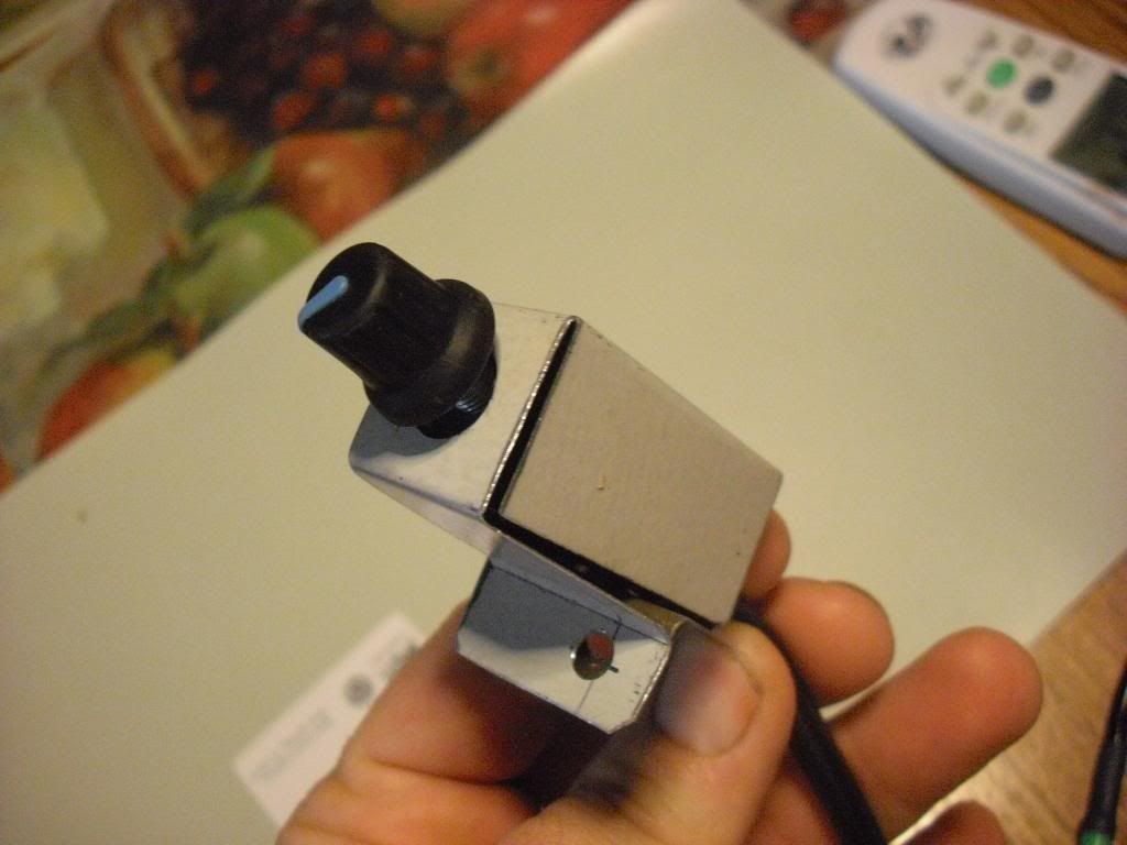
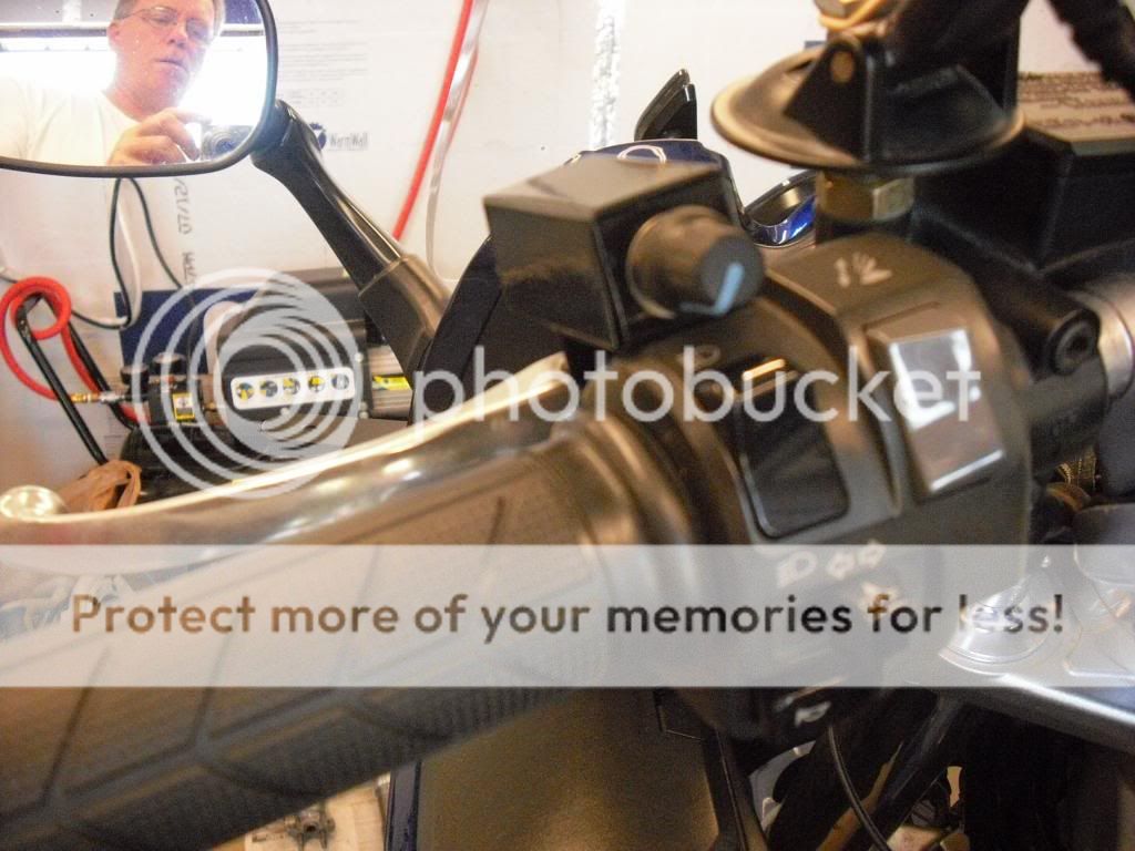
A couple coats of gloss black paint, and it's ready to go in:
Installed exactly where I want it... ignore that fool in the mirror...
So, on to the rest of the install. After removing the four inner panels I put the brackets on. They were supplied free with our group buy from Clearwater. Here I'm tightening one of the mirror nuts
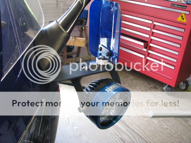
I mounted the Kristas a little differently as I have a set of Baker air wings that need to go on as well. This was a lot more difficult than it looks. 3 separate trips to the Hardware store and many hours of trial and error. This combination looks like it should work pretty well:
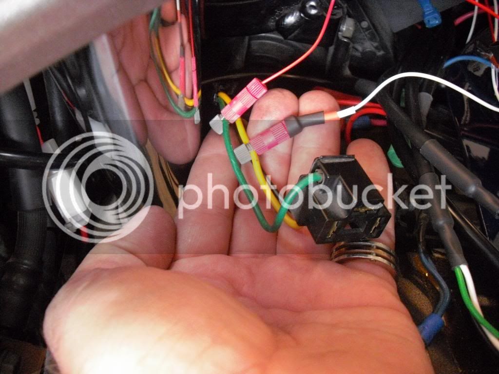
This attempt to take a short cut was a disaster. On the phone with Glen from Clearwater, I learned that tapping this green wire for a switched source (sends the signal to trip the relay that turns on the Kristas) was a bad idea. The Gen 1, which uses H4 bulbs, shuts off the low beam when the high beams are activated. However, tapping the yellow high beam light here worked out fine: I ended up removing the red trip wire from the green low beam wire, per Glen's instructions.
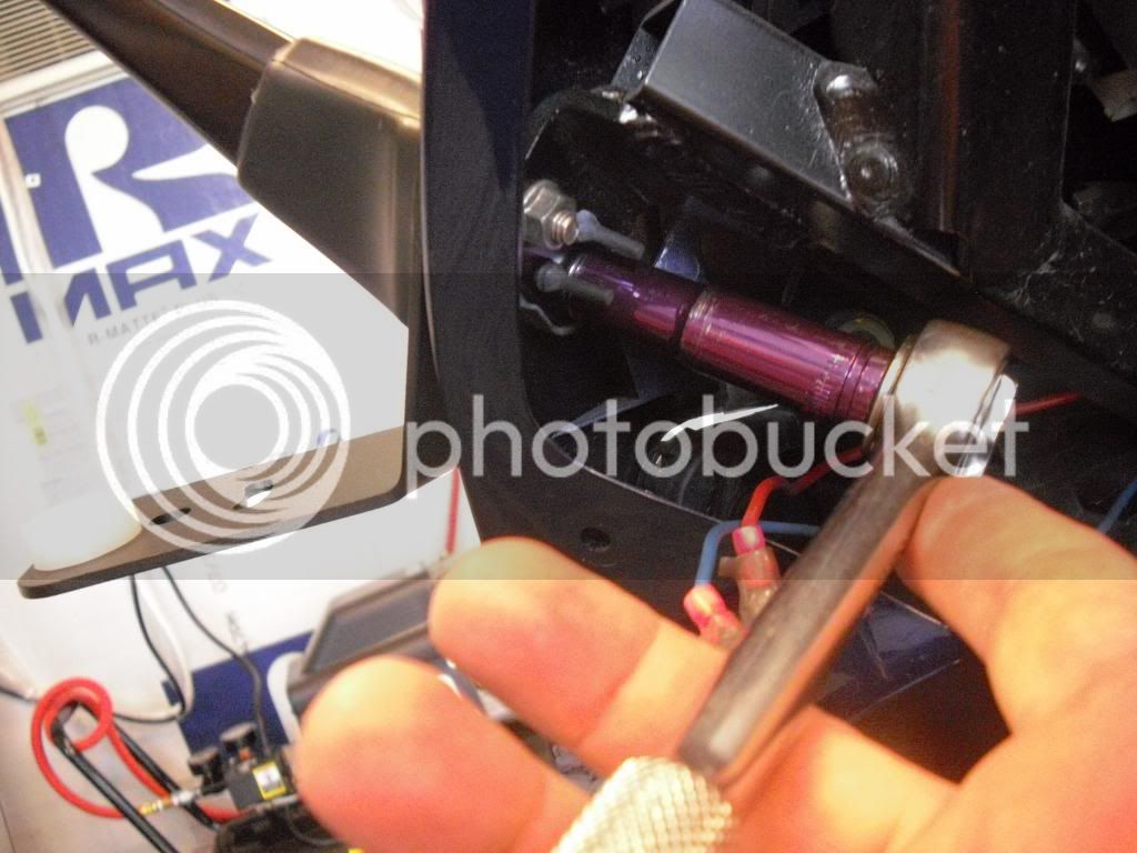
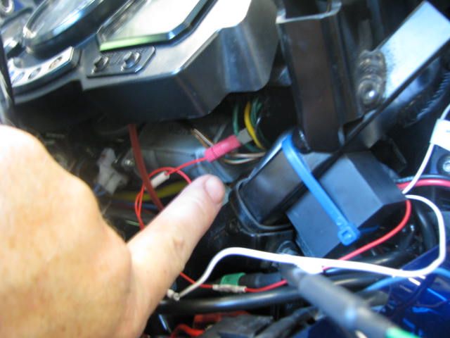
Below is the finished job. Here I tapped into the green wire with the blue stripe coming from the headlight relay, like I was supposed to. It's located just above the wires I'm pointing to. You'll also notice that I strapped the Clearwater module to one of the FJR steel rails with a blue zip-tie-- just to the right of my finger below.
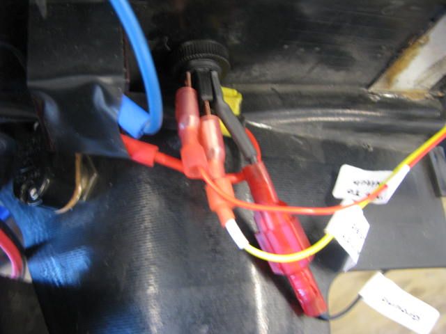
Next I drilled a 1/2 inch hole in one of my panels for the Clearwater's on/off switch with its little red LED light...and wired it up with the red, yellow, and black wires per Clearwater instructions.
Hooked up the battery, tested it out, and everything's working great. Sure did appreciate the help Glen from Clearwater gave me over the phone. I also learned something: Do not try to tie into the horn on the Gen 1. It cannot be used to trigger the Kristas as the instructions say. This is directly from Glen at Clearwtaer.
At one point during the installation, I feared that I'd fried the circuit board due to my wiring mistakes. Glen gave me a VERY generous offer to replace it for a reduced price, though I lucked out and it turned out that a weak ground produced some weird symptoms that caused him to suggest that maybe I'd fried the circuit board. Turned out that everything was just fine, once I got the thing properly grounded.
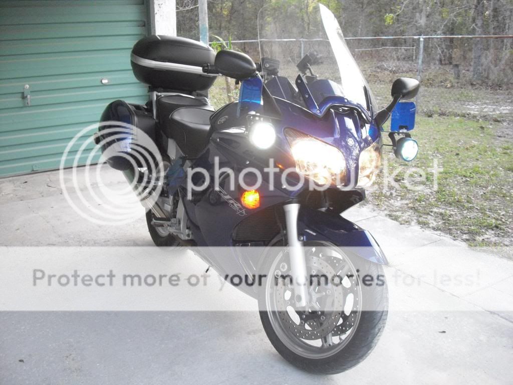
They are seriously bright. I'll need to do a little more adjusting, but I'm a happy camper.
Gary
darksider #44
Getting them off was a challenge as the factory puts them on pretty snug. I used a vise... and an oil filter wrench. I wrapped the lens with a couple layers of masking tape to prevent damage. However, I learned that the white logos come off when using this method. Look closely at the black bezel. Notice that part of the Clearwater logos came off. Good thing I don't need to keep these black bezels. Do yourself a favor and have 'em done at the factory before you order them. I simply hand tightened the blue bezels.
I didn't like the factory supplied "box" supplied for the dimmer control. So I decided to fab up my own. I started with doing a little measuring, then i drew it out on a piece of card stock paper:
I cut it out and then traced it onto a piece of sheet metal:
First i drilled the holes. You'll notice that the front and back are off center a little. This is to accommodate the shape and location of Clearwater's switch...
One of the two larger holes (the one on the left) was supposed to be a lot smaller, but a decent sized washer cured the problem later on.
Anyway, next, I cut it out and filed the edges:
Then it was time to do some bending. I wanted to make it so that the flange was located on the bottom, with the hole slightly off to the side so that it would fit right where i wanted it to go... If I had it to do again, I would have made it about 1/4 inch shorter. Oh well.
Below, right next to my finger you can see the factory screw ready to be replaced by a longer stainless cap screw and an appropriate sized sleeve (available at any hardware store):
A couple coats of gloss black paint, and it's ready to go in:
Installed exactly where I want it... ignore that fool in the mirror...
So, on to the rest of the install. After removing the four inner panels I put the brackets on. They were supplied free with our group buy from Clearwater. Here I'm tightening one of the mirror nuts
I mounted the Kristas a little differently as I have a set of Baker air wings that need to go on as well. This was a lot more difficult than it looks. 3 separate trips to the Hardware store and many hours of trial and error. This combination looks like it should work pretty well:
This attempt to take a short cut was a disaster. On the phone with Glen from Clearwater, I learned that tapping this green wire for a switched source (sends the signal to trip the relay that turns on the Kristas) was a bad idea. The Gen 1, which uses H4 bulbs, shuts off the low beam when the high beams are activated. However, tapping the yellow high beam light here worked out fine: I ended up removing the red trip wire from the green low beam wire, per Glen's instructions.
Below is the finished job. Here I tapped into the green wire with the blue stripe coming from the headlight relay, like I was supposed to. It's located just above the wires I'm pointing to. You'll also notice that I strapped the Clearwater module to one of the FJR steel rails with a blue zip-tie-- just to the right of my finger below.
Next I drilled a 1/2 inch hole in one of my panels for the Clearwater's on/off switch with its little red LED light...and wired it up with the red, yellow, and black wires per Clearwater instructions.
Hooked up the battery, tested it out, and everything's working great. Sure did appreciate the help Glen from Clearwater gave me over the phone. I also learned something: Do not try to tie into the horn on the Gen 1. It cannot be used to trigger the Kristas as the instructions say. This is directly from Glen at Clearwtaer.
At one point during the installation, I feared that I'd fried the circuit board due to my wiring mistakes. Glen gave me a VERY generous offer to replace it for a reduced price, though I lucked out and it turned out that a weak ground produced some weird symptoms that caused him to suggest that maybe I'd fried the circuit board. Turned out that everything was just fine, once I got the thing properly grounded.
They are seriously bright. I'll need to do a little more adjusting, but I'm a happy camper.
Gary
darksider #44
Last edited by a moderator:

") Nice job!
Nice job!