How to check R/R voltage on a Gen II?

Yamaha FJR Motorcycle Forum

Help Support Yamaha FJR Motorcycle Forum:

This site may earn a commission from merchant affiliate links, including eBay, Amazon, and others.
allrighty then- my trusty Datel shows bat v gradually dropping from 14 to 13.9 to 13.8...
That may not be entirely true. Under different operating conditions there was often a significant discrepancy between what my Datel read for voltage and what my DMM showed when they both were directly across my battery terminals. I have put an O'scope on my Gen I and found a lot of 'noise' on the +12 volt line. Different meters deal with the noise in different ways resulting in different readings, this is one time where an old school needle type meter may actually provide a more accurate reading.(1) I would very much like to have a chance to put an O'scope on a few electrical systems to see what is truly going on.

(1)Since it's Friday I'll spare y'all a long, dry, boring explanation of why :)
Aw, go on! I'm already bored.
 
Last edited by a moderator:
The Red/Black DC wires from the R/R go to the starter relay where they attach to a heavy threaded studs. The two studs are the points where the smaller gauge R/R wires connect to the heavy gauge battery wires.
There is no need to do anything with the three gray AC wires that connect to the stator unless the DC voltage at the R/R is low while the Red/Black output wires are connected to the R/R. If the basically nominal load on the electrical system causes the DC output of the R/R to be low then it's time to troubleshoot the stator and R/R.
So I'm needing to ask when you say both wire go's to the heavy studs? Aren't both studs positive? One stud connects strait to the positive on the battery and the other sends power to the starter.

I may have misunderstood Jack's instructions but I have the Red wire going to the Positive Pole and the Black going to the Negative pole on the battery. Also have been up and running for a few months with a couple of five hundred mile days and no issue's

 
Last edited by a moderator:
SkooterGThe R/R on the GenII is located near the rear shock, you don't need to remove any parts to get to it.

You'll find that your problem is most likely the one many of us GenII owners have faced before, it's due to the cheap-ass underrated wiring Yami used for this circuit.

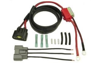
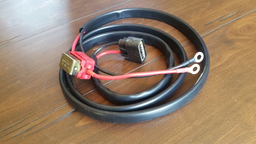
The solution is to bypass the OEM wiring going from the R/R to the Battery with a min. 12AGW wiring, for both +ve & -ve leads. You can choose to use either a regular fuse or a circuit breaker (they are both about the same size).

Dcarver did a lot of research on this a few years back and has documented it very well on the forum, I just don't have a chance right now to search for it.

You can of course scrounge up the needed parts from eBay, etc. or Jack makes a complete plug & play kit for this with the circuit breaker included.

Super harness with 30 amp circuit breaker

https://roadstercycle.com/index.htm

Super_harness_cb_wb_irf.jpg

Thanks!

So I have found the R/R. Looking from the left side of the bike, which connector is the output? Left or right? (Damn I wish I had my SM!) I assume I unplug the output connector and check voltage on the R/R where I unplugged it? From my forum search, I should have 15.4V.

Yes, I have a trusted technical source within Yamaha who was almost willing to bet me it was degraded wiring from the R/R to the battery. (The same thing happened to his '06 FJR) I am getting 13.1-13.4v at the battery terminals.

Since I am going through a move it's difficult to work on my own shit right now, and will be for some time. The 09 was a few days within the 5 year Y.E.S so I took it to a dealer. I told them what was going on and what I suspected. After having it two weeks they returned it to me and told me everything checked out ok - 14.0+ volts everywhere. WTF?!?!?!?! Before I left I had the service manager check the battery terminal charging voltage and his POS voltmeter was bouncing around but reading around 13.4v. He just stared blankly at me. Fuck them, I brought it home and verified I am still at a charging voltage of 13.1-13.4v at the battery terminals. I want to verify my R/R output voltage is correct so I can take it back to them and tell them to fix this POS Gen II FJR correctly this time and do it for goddamned free under the extended warranty!!! Grrrrr.......

Perhaps I'll just fix it myself with that nifty kit you provided info for. Thanks! But this weekend the g/f, I, and her 21 year old son move into an 1100 sf apartment with no freaking garage until we find a house to buy. My life sucks. I keep telling myself that in 3-6 months all will be good.

I vaguely remember Carver's thread and the wealth of research and information it supplied but as of yet haven't found it.
@ScooterG, just buy the R/R kit I linked to from Jack and install it, it's really easy (pretty much plug & play) so you will not need much in the way of tools. I opted for the 50A circuit breaker (and 10AWG wires) rather than the 30A one he's got listed, you just need to ask him for the 50A version... Honestly I think 12AWG wires with the 30A breaker will be totally sufficient.

If you do this mod It will be a one-time permanent fix!

I've had this setup running for over 100k miles now, and am always getting around 14.2V on the Datel with the normal load, well plus a bunch of little farkles that are always on. Even with the 2x30W LED Aux lights and the Baja HID lights on I still get around 13.9-14V at the Datel at around 2500+ RPM.
There comes a point, and we've passed it, of diminishing returns. Given this logic, why not get a kit with 00AWG and a 1000 amp breaker?

The simple reason is that if for some strange reason your battery suddenly wants that many amps, you have much bigger problems and "Smoke and Fire" will be two of them.

These little VRLA motorcycle batteries are unlikely to ever desire more than about 10 amps of charging current, and if they desire more it is because they are failing and/or about to go into thermal runaway.

That being the case, a 50 amp CB is a recipe for disaster.

Bigger is not always better.

JSNS

 
Last edited by a moderator:
And yet another thought.................INEWLF mentioned that his battery voltage drops from 14.0 to 13.9 to 13.8 V. I have always seen the same thing occurring since day one with my '05. It is especially noticeable when it's warmer outside, temps say in the 80's. I think that is due to the effect of heat on the output of the alternator and also possibly the RR. IF it's a rather cool day, say outside temps in the high 50's/low 60's, the battery voltage starts out about 14 V and after the enging fully warms up the voltage drops to about 13.9V. Also pretty much constant over the normal riding RPM range. BTW, those voltage values are measured with the DATEL meter and when the battery is fully charged when starting out. If the batter is slightly discharged when starting out then the initial battery voltage indications are say about 13.8 and slowly rising to the 13.9 to 14.0 volts after a short while as the battery charges. Just FYI, I am using a Shorai battery (2nd one in 8 years) but noticed similar battery voltage characteristics when I was using the factory Yuasa battery.

Anyway, that's my experience. Your results may be different!

 
Jeeze... You electrical guys are something else. More power (pardon the pun) to you guys. I read this whole thread and I didn't understand a single word. Enjoyed reading it, though!
nyam.gif
yes.gif


Last edited by a moderator:
The current from the Alternator through the R/R is not just recharging the battery. It is also providing all of the power needed to run the bike and any and all accessories that you have added to the bike. You need to size any fuse or breaker and the wires that carry the current to accommodate your full expected load current.

Do not be confused into thinking the bike is running off the battery and we are just recharging that. The battery is just a very large capacitor. It is an electric power storage device and is only really "used" or supplying power when the bike is not running, i.e. to start the bike.

Once the bike is running the voltage from the alternator is higher than the battery voltage, so the bike runs off that power while simultaneously recharging any power lost from the battery running the starter motor. Once the battery is fully charged it just sits there. THat is unless you place so much of a load (current demand) on the system that the alternator output begins to sag. When the alternator voltage sags below the battery voltage you start to discharge the battery and it will not be able to start the bike the next time you require it to.

 
Last edited by a moderator:
The current from the Alternator through the R/R is not just recharging the battery. It is also providing all of the power needed to run the bike and any and all accessories that you have added to the bike. You need to size any fuse or breaker and the wires that carry the current to accommodate your full expected load current.
Do not be confused into thinking the bike is running off the battery and we are just recharging that. The battery is just a very large capacitor. It is an electric power storage device and is only really "used" or supplying power when the bike is not running, i.e. to start the bike.

Once the bike is running the voltage from the alternator is higher than the battery voltage, so the bike runs off that power while simultaneously recharging any power lost from the battery running the starter motor. Once the battery is fully charged it just sits there. THat is unless you place so much of a load (current demand) on the system that the alternator output begins to sag. When the alternator voltage sags below the battery voltage you start to discharge the battery and it will not be able to start the bike the next time you require it to.
Maybe, to a certain degree. But every load you add to the system, i.e. aux lighting, heated gear etc. IS running off the battery. And now the job of the alternator is to keep the battery at a net loss of zero amps. AMPS not VOLTAGE The voltage from the alternator is higher, yes, and is, or at least, should be, constant. This is known as the "float" voltage. It is the alternator Amperage which determines the battery "charge". No load on the battery and the voltage remains the same, i.e. at the "float" level. It is the amperage which will drop to the level demanded by the existing load, be that the factory load or the factory load plus any accessories you've added.

None of this really matters since the question is 30 amp harness vs. 50 amp harness. Given the fact that the alternator likely puts out far less than either of those figures I supect the question and answers are moot.

 
^^^^^^^
ermm.gif
Most of the right words are there but the sequence they come in doesn't look quite right....

The fuse just determines the point in which the system protects itself. If the fault is a primary power supply short then the amperage of the fuse really doesn't matter much because even a 75 amp fuse would blow. If the problem is excess current draw to to failing electronics or a silly amount of electrical add-ons the fuse value will matter. Slightly excess current may take a long time to melt a fuse. When a fuse does it's job due to a short, looking at the fuse you will see a black burned area with perhaps a metal sheen. When there is excess current draw the center of the fuse will be melted open in a little gap.

Wire ampacity to wire gauge is not a straight number, it is arrived at by measuring the temperature rise of the wire as the current goes up. At some point the temperature rise becomes unacceptable so the current specification for that wire gauge is set below the excess temperature point. The ampacity/gauge is also grouped into categories like the wires being run in free air, in bundles or in raceways. The less air flow, the lower the current rating for a given wire gauge. A wire can be 18 gauge in free air but for the same current it may need to be 14 gauge if being used in a raceway. As the wire heats up the resistance goes up which impedes current flow and the limited current generates more heat in the wire until something intercedes or something breaks (smoke).

The issue becomes more about how the connector pins are affixed to the wire, this is the significant resistance point in the wire run. This is why when you have a wire failure due to heat it happens at the ends and not in the middle
smile.png
Solder is golden when done correctly. Crimping can be just about as good as long as the correct crimper die is used for the pin style and wire gauge. There are lots of thing that can go wrong with wire crimping, hopefully the person doing the job is a professional with professional tools.

 
Last edited by a moderator:
Yeah, sorry... it doesn't quite work that way.

As long as the output voltage from the alternator is higher than the battery internally stored voltage, all of the electric power (current) for running the bike and accessories is coming from the alternator and bypassing the battery altogether.

But it doesn't really matter. You have the right idea. The net current in and out of the battery is zero, but the net current from the alternator is whatever the load requires.

The second Gen alternator is capable of producing 590 watts, which is roughly 42 amps at 14VDC. I would want to have a bigger than 30 Amp circuit breaker in series with my alternator if I were to do that mod.

For the record, in the stock wiring configuration there is no circuit breaker or fuse in series with the full load current from the alternator. The loads split into separate fuses before they head off to the various loads.

 
Last edited by a moderator:
Yeah, sorry... it doesn't quite work that way.
As long as the output voltage from the alternator is higher than the battery internally stored voltage, all of the electric power (current) for running the bike and accessories is coming from the alternator and bypassing the battery altogether.

But it doesn't really matter. You have the right idea. The net current in and out of the battery is zero, but the net current from the alternator is whatever the load requires.

The second Gen alternator is capable of producing 590 watts, which is roughly 42 amps at 14VDC. I would want to have a bigger than 30 Amp circuit breaker in series with my alternator if I were to do that mod.

For the record, in the stock wiring configuration there is no circuit breaker or fuse in series with the full load current from the alternator. The loads split into separate fuses before they head off to the various loads.
Then why is it that we run our accessories off the battery and not off the alternator.

 
Then why is it that we run our accessories off the battery and not off the alternator.
The alternator is AC, the R/R converts the AC to DC and then regulates the output to be not more than 14.xx volts. Outside of wire length, it is the exact same thing as to connect the motorcycle main power circuit directly to the R/R or the battery. It does matter to the starting circuit which requires the big cables from the battery to the starter relay.

 
Last edited by a moderator:
As ionbeam said, connecting at the battery or the output from the R/R is electrically the same thing. So, to answer the question: The reason we hook up at the battery is because it is a much easier place to hook things up to.

 
As ionbeam said, connecting at the battery or the output from the R/R is electrically the same thing. So, to answer the question: The reason we hook up at the battery is because it is a much easier place to hook things up to.
True, in an ideal situation. Perhaps I am mistaken but I thought the purpose of the harness was to eliminate voltage losses between the R/R and the battery due to too high gauge wire and connections along the way? Or is the replacement/auxiliary wiring for a different purpose?

I am wondering if my high mileage '07 is suffering along the same lines. Going to have to dig out the meter and do some checking.

 
The Red/Black DC wires from the R/R go to the starter relay where they attach to a heavy threaded studs. The two studs are the points where the smaller gauge R/R wires connect to the heavy gauge battery wires.
There is no need to do anything with the three gray AC wires that connect to the stator unless the DC voltage at the R/R is low while the Red/Black output wires are connected to the R/R. If the basically nominal load on the electrical system causes the DC output of the R/R to be low then it's time to troubleshoot the stator and R/R.
So I'm needing to ask when you say both wire go's to the heavy studs? Aren't both studs positive? One stud connects strait to the positive on the battery and the other sends power to the starter.

I may have misunderstood Jack's instructions but I have the Red wire going to the Positive Pole and the Black going to the Negative pole on the battery. Also have been up and running for a few months with a couple of five hundred mile days and no issue's


Been a busy little boy and am finally getting back to this. Almost immediately decided to fix this myself and purchased the wiring harness from Jack. No instructions came with it. Am hoping to get this done sooner than later.

Where do I connect the ends of the harness to?

My pretty new harness:

20160606_133447_zpshh0gtxf2.jpg


Really? Did you not carefully read my 100 page post and watch all 20 videos?

Ring lugs directly to battery.

Other fancy-nancy connector directly to RR.

JSNS and
fuck.gif


Hugs n' Kisses

 
I just completed a mod on my '05 related to this. I noticed over the last 4-5 months that the battery voltage being shown on the Datel meter was not what I remember. It was showing about 13.9 volts nominal at start up and after the engine warmed up it would drop to about 13.6 -13.8 volts. Started a little trouble shooting and verified that the voltage displayed on the Datel was indeed the actual battery voltage. BTW, the battery was new (Shorie). I then found the main fuse (50 amp one, damn why did Yamaha hide that thing in front of the battery?) and removed the fuse and made sure the fuse and fuse holder had good connection. THe voltage at the battery remained as I described. Next I probed the black and red wires at the R/R and found the voltage to be 14.3-14.4. Apparently some where along the way there must be excessive resistance . To improve this situation I hooked up 2 additional wires from the R/R to the battery. Used # 12 awg wiring and a 40 amp fuse. Problem solved. Voltage now at the battery is 14.3-14.2 at all times and I'm happy again!

 
I just came across this problem myself. I have a Datel DVM and noticed it go from 14v idle 6 mo ago, to a 13.1v idle. First thing I did was buy a new battery. I couldn't find a date on the battery, so I just assumed that was the cause. Borrowed a friends Fluke DVM. Found 13.1v-13.7v at battery, idle and rev. found 14.7v at RR at idle. Will be buying new harness soon! Anyone have description of how to accomplish installation?

 
I just came across this problem myself. I have a Datel DVM and noticed it go from 14v idle 6 mo ago, to a 13.1v idle. First thing I did was buy a new battery. I couldn't find a date on the battery, so I just assumed that was the cause. Borrowed a friends Fluke DVM. Found 13.1v-13.7v at battery, idle and rev. found 14.7v at RR at idle. Will be buying new harness soon! Anyone have description of how to accomplish installation?
See Above Dcarver Post

Really? Did you not carefully read my 100 page post and watch all 20 videos?

Ring lugs directly to battery.

Other fancy-nancy connector directly to RR.

JSNS and
fuck.gif


Hugs n' Kisses
 
Last edited by a moderator:
Top