Audiovox CCS-100 cruise control installation

Yamaha FJR Motorcycle Forum

Help Support Yamaha FJR Motorcycle Forum:

This site may earn a commission from merchant affiliate links, including eBay, Amazon, and others.
I am installing my AVCC and have read all the write-ups and have a question still...do I hook up the vucuum hose to the throttle bodies themselves or do I hook them up to the valve where you check your valve alignment?
you hook up your vacuum line(s) to the nipples on the throttle bodies where you do the throttle body sync (TBS)

Throttle Body Sync with pics of the nipples

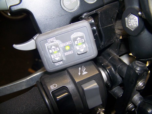
I used grey RTV, oxygen sensor safe, to seal up my control pad

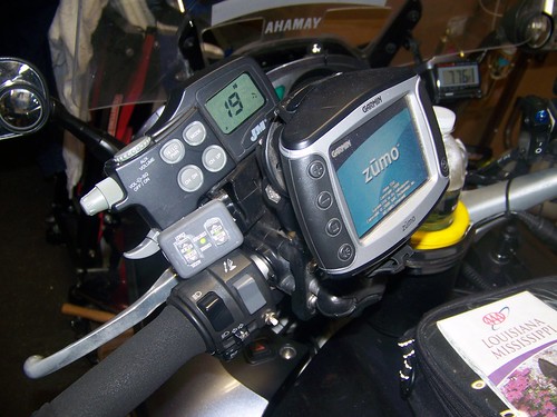
WFooshee above (Walter Fooshee) was kind enough to invite me to his home garage shop in Panama City and did the AVCC install as well as changing my plugs to my provided Iridiums and a Throttle Body Sync while the tank was propped up.

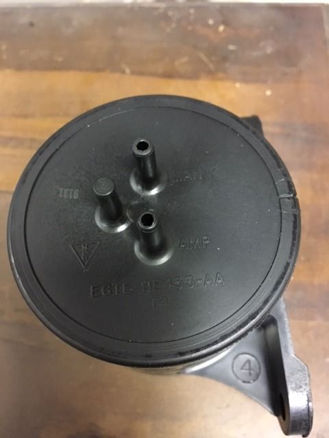
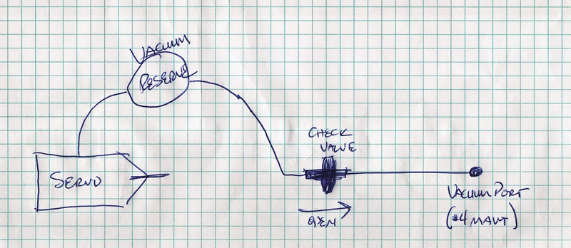
Mine has one vac connection with one check valve and a Luber Finer FF3404 fuel filter for a vac cannister.

This thread was helpful to me: Good summary AVCC install thread

3229123869_a3ecca71fe.jpg


3229123863_719485fcc3.jpg


Best of luck,

Mike in Nawlins'

 
Valve alignment? Is that checked when muffler bearings go bad?
There are four rubber caps on the rail across the top of the throttle bodies. Pick one. That's it.

Some folks rig up a series of check valves and use all four. The check valves are so they don't "see" each other.
Yes when the muffler cracks that is exactly when you would need to do a valve alignment...thank goodness i didn't post that on Friday <_<

 
Well I tried deleting my post about my cruise not working and couldn't figure out how.

 
Last edited by a moderator:
Thanks Gordon for a great write-up. You provide clear, easily understood text with good pictures...a basic for "how to" technical writing. Ironically I started installing my Audiovox CC100 this past weekend working with a previous model install write up by Amain in 2003. But my '09 with ABS has lost all of the cubbyholes that he used especially for the servo and reservoir tank. Plus I was slowed by the removal of the basic things like the fuel line from the tank and the complex fuel rail assembly. Yamaha makes one of their gasoline connectors "orange" so you would think that that was the connector you were supposed to remove. :blink: After gently prying and pulling for about a 1/2 hour I finally disconnected the black one with ease. So much for good logic. ;) But with limited time available I reluctantly gave up and put the bike back together.

Now that I have found your write-up I will plunge back in with new ideas and confidence. And also, IMHO vacuum is vacuum and I don't think there is enough volume being depleted to affect the MAP sensor or anything else no matter where you pick the the supply.

Bill

 
...And also, IMHO vacuum is vacuum and I don't think there is enough volume being depleted to affect the MAP sensor or anything else no matter where you pick the the supply...
This is one of the assemblies in the servo. These are solenoids that control the vacuum that moves the vacuum diaphragm which controls the servo cable and thereby the speed. I understand that on more recent servos the DUMP solenoid has been eliminated. As the AVCC works it is continually venting some amount of vacuum.

Solenoids.jpg


Last edited by a moderator:
Prepare the servo unit for installation: (sorry I don’t have pictures for the next few steps)1) Remove the 2 screws holding the access cover in back of the servo unit and remove cover.

2) Remove main wiring harness. Note what position it came off. Although there’s a locking tang, it does not look totally fool proof.

3) Cut off and discard the separate harness (wrapped together) grey and black wires. Only cut the wires that are wrapped together and not the bigger black wire in the main connector of the servo unit harness. This is only used for vehicles with VSS (vehicle speed sensor). Since we will be operating on engine speed only (tach signal) this will not be needed.

4) Set the 7 dip switches inside the servo unit as follows: #1, #4, #7 in ON position. #2, #3, #5, #6 in OFF position.

5) Reinstall main connector and resecure cover. Make sure wires are spread out in order to have good seal.
So I noticed something here that either no one has picked up on or I am misunderstanding (probably the latter.)

Gordon doesn't mention removing the Jumper for manual transmissions. Am I incorrect in my thinking that this needs to be done?

As an editorial note: The wiring harness I have was not connected to the unit when I received it and it is not possible to put it on backwards.

 
I thought I would add a thoroughly stupid question so that everyone can gang up and make fun of me.

Is the vacuum check valve is installed on the vacuum canister, or in front of the servo? Also, which way does the valve flow? To maintain a vacuum in the canister I assume?

Thanks, and let the abuse begin.

Found it, nevermind - now let the abuse begin about using the "Search" function.

 
Last edited by a moderator:
[Abuse]

The check valve would be between the vacuum source and the canister, and with the arrow pointing towrd the vacuum source, so as to maintain vacuum in the canister.

The canister's not much good if it's allowed to go with the intake pressure rather than holding vacuum.

[/Abuse]

:D

 
So I noticed something here that either no one has picked up on or I am misunderstanding (probably the latter.)Gordon doesn't mention removing the Jumper for manual transmissions. Am I incorrect in my thinking that this needs to be done?
OK, I found it on FJR1300.info and it is as I expected. I would hope that most people would catch that but it could be missed if someone ignored the instructions that came with the unit in lieu of these. If Gordon is still around, an edit to your procedure would probably be in order.

Time for another stupid question...

What size is the bike wiring for brake lights, tail lights and at the ECU? Want to get the right Posi-Taps!

 
I am currently re-doing some of the CC plumbing and adding a vacuum canister so was looking over the various Vista cruise writeups. I'm a little confused regarding the vacuum canister/reservoir hookup since I can see it connected in parallel in this write-up and in series in the other write-up. I guess my question is does it really matter? Or is it based on whether or not the vacuum reservoir I'm using has two or one outputs.

I already have two vacuum hoses with check valves on two of the TBS ports.

I'm going to be using this reservoir which has the MAN (goes to the Manifold side) and AMP (goes to the Servo side) connections, thus I think I need to hook it up in series with my CC Servo, i.e. before the Servo.

Would appreciate some input, from you guys, thanks.

IMG_9230.jpg


The diagram below is from the install Kaitsdad did, and depicts the reservoir connected in series with the servo. From the installation summary thread:

https://www.fjrforum.com/forum//index.php?showtopic=113397

301798561_MgVRx-L.jpg


The image below is from the install GordonFJR did and depicts the reservoir connected in parallel with the servo.

IMG_9691.jpg


Last edited by a moderator:
The supplied reservoir is designed to be used in series with from a single vacuum port. On my installation I used one port, relying on the reservoir's check valve. Worked fine.

With two ports, you'd need to have a check valve on each of those, T them into the "Man" port on the reservoir, and finally connect from the "Amp" port to the actuator. I see no advantage in using this, but you might get away without the reservoir altogether. You could certainly discard it if you used all four vacuum ports.

You could put the reservoir in parallel with the T'd feed to the actuator, but I see no advantage. Here you'd use the "Amp" port, leave the "Man" port open (or blocked off if you didn't trust its check valve). You could even add another vacuum port to the "Man" port if you really wanted to.

 
Last edited by a moderator:
The vacuum reservoir can be series or parallel, ie, a fuel filter will work, providing your check valve is on the throttle body side of the equation. You could experiment without a reservoir. Some apparently just used a few feet of hose curled up, so it wouldn't appear necessary to have a huge reservoir.

 
Thanks for the suggestions guys, per Mcatrophy's post, I'll go ahead and hook up my reservoir in series, b/w the throttle bodies and the CC servo. I already have check valves in place on the two TBS ports that are providing the vacuum.

 
Top