Should I simply adjust them up proportionally?Running off the alternator at 13.8V instead of the battery's @12.6V will result in slightly higher currents.Here are some numbers for you RZ. Hope this helps.
Fan Amperage Draw
10A in rush with 4.7A constant (1 fan measured, using DVM so inrush could be a little higher.)
Horn
2.2A constant
Headlight
5.1A constant for the Hi Beam
4.6A constant for the Low Beam
These numbers were obtained by running wires direct from the battery so they do not include relay and system loses.
You are using an out of date browser. It may not display this or other websites correctly.
You should upgrade or use an alternative browser.
You should upgrade or use an alternative browser.
FJRF009.0: Ground Spider Research
- Thread starter bramfrank
- Start date


Help Support Yamaha FJR Motorcycle Forum:
This site may earn a commission from merchant affiliate
links, including eBay, Amazon, and others.
- Status
- Not open for further replies.
charismaticmegafauna
Well-known member
Won't operating at slightly higher voltage result in slightly lower current draw (if power consumption/wattage of the load remains the same)?Running off the alternator at 13.8V instead of the battery's @12.6V will result in slightly higher currents.Here are some numbers for you RZ. Hope this helps.
Fan Amperage Draw
10A in rush with 4.7A constant (1 fan measured, using DVM so inrush could be a little higher.)
Horn
2.2A constant
Headlight
5.1A constant for the Hi Beam
4.6A constant for the Low Beam
These numbers were obtained by running wires direct from the battery so they do not include relay and system loses.

S76
Well-known member
Running off the alternator at 13.8V instead of the battery's @12.6V will result in slightly higher currents.Here are some numbers for you RZ. Hope this helps.
Fan Amperage Draw
10A in rush with 4.7A constant (1 fan measured, using DVM so inrush could be a little higher.)
Horn
2.2A constant
Headlight
5.1A constant for the Hi Beam
4.6A constant for the Low Beam
These numbers were obtained by running wires direct from the battery so they do not include relay and system loses.
Good point. I hadn't thought of that. But I think it would actually lower the current a tiny bit wouldn't it? That would make my measurements about 10% to high compared to an "engine running" condition.
Edit: But then again it is so freaking cold up here and the bike has been in the basement for so long that my memory does not go back to a time when there was an "engine running" condition. 2 more long dismal months to go. Ugh.
Last edited by a moderator:
FRJ Jc
Well-known member
I like both ideas. I will be updating my headlights with an HID set, which will hopefully help. I just might of killed two birds with one stone... lighting farkle fixes my connector issue. LOVE IT!!!And maybe do the same to each existing headlight ground?No electrical wizzard here, but IMHO the fix in post #255 might be better than the one in #258? Soldering a ground wire to the spider still allows all current to pass thru the spider itself,whereas grounding the fans seperatly removes some of the load. In the interest of not hacking up the harness,one could use a posilock line tap on each of the fan ground wires and run a wire to chassis ground for each, thereby providing additional paths for both the fans and the spider without cutting wires..What think?
vabrzn
Well-known member
I did the same thing minus putting the black cover back on, have had no issues, where on the chassis did you place the ground wire?
I went ahead and ran to my fuse block.
Just food for thought...
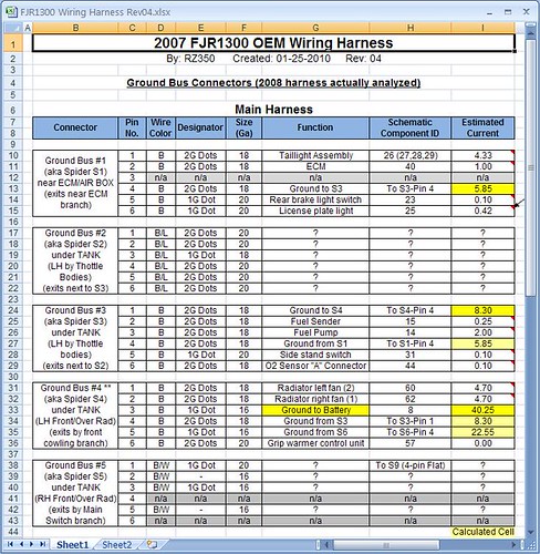
My table shows the ground bus system has everything flowing into S4 from two distinct “upstream” paths. The wires progressively get bigger flowing into S4 to handle the increasing load. This makes perfect sense and hopefully everyone can see that.
If we add one new ground path at S1, for instance, we now have 2 paths in the system for the current to flow and some of the current may actually be flowing the opposite way through the harness wires to S1. This could possibly overload the harness wiring near S1 that now becomes a heavily-loaded “downstream” wire, instead of the lightly-loaded “upstream” wire as originally intended. Some of those “upstream” wires are small 18ga size. Although the amount of current flowing through the different ground paths can be calculated, my table doesn’t consider two paths. Remember the old saying “path of least resistance”? The current from each component will have a choice as to which ground path to take and its current flow may actually split between the paths.
I have not devised my actual plan of attack yet, but I was considering adding extra ground wires when time permits (when I have that part of the bike apart for other work), but I think I need to be careful doing that. I may have to do them all at once, or at least in a systematic order, starting at S4 and working my way “up” the chain.
Just a caution to everyone.
mcatrophy
Privileged to ride a 2018 FJR1300AS
Headlight current won't change much, their resistance goes up with temperature (which is why they take a huge current surge when turned on, but probably too quick for Fred's DVM to show).Should I simply adjust them up proportionally?Running off the alternator at 13.8V instead of the battery's @12.6V will result in slightly higher currents.Here are some numbers for you RZ. Hope this helps.
Fan Amperage Draw
10A in rush with 4.7A constant (1 fan measured, using DVM so inrush could be a little higher.)
Horn
2.2A constant
Headlight
5.1A constant for the Hi Beam
4.6A constant for the Low Beam
These numbers were obtained by running wires direct from the battery so they do not include relay and system loses.
Horns and fans I would expect current to be near proportional. But, allow (say) 0.25V drop for relay contacts.
Personally, I don't think a few percent either way is significant. We're talking about corrosion leading to resistance, which will self-heat with any reasonable current. It's a vicious escalating circle, once it's started, it's fubared.
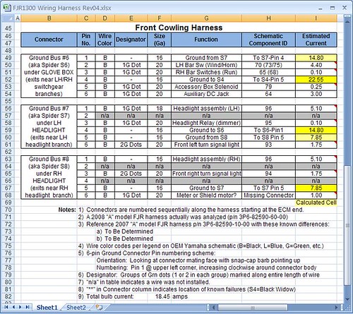
Revision 04 of the table follows at the end. I made the adjustments per measured amps by S76. To keep it simple, I didn’t bother compensating for the higher system voltage. With the higher voltage however, I do suspect bulb current remains the same (constant power device), but the fan and horn current goes up slightly with voltage (constant resistance device).
In this condition we get the following total amperage on the individual spiders:
S1= 5.85
S3= 8.30
S4= 40.25
S6= 22.55
S7= 14.80
S8= 7.85
The following could be considered a more “normal” riding condition. I turned off fans, horns, and turn signals (still have 3A on acc port):
S1= 2.35
S3= 4.80
S4= 19.45
S6= 14.65
S7= 11.30
S8= 6.10
Worst Case Scenario:
road runner
Well-known member
This may have some merit, although the shorter path may also be of less resistance.Just food for thought...
My table shows the ground bus system has everything flowing into S4 from two distinct “upstream” paths. The wires progressively get bigger flowing into S4 to handle the increasing load. This makes perfect sense and hopefully everyone can see that.
If we add one new ground path at S1, for instance, we now have 2 paths in the system for the current to flow and some of the current may actually be flowing the opposite way through the harness wires to S1. This could possibly overload the harness wiring near S1 that now becomes a heavily-loaded “downstream” wire, instead of the lightly-loaded “upstream” wire as originally intended. Some of those “upstream” wires are small 18ga size. Although the amount of current flowing through the different ground paths can be calculated, my table doesn’t consider two paths. Remember the old saying “path of least resistance”? The current from each component will have a choice as to which ground path to take and its current flow may actually split between the paths.
I have not devised my actual plan of attack yet, but I was considering adding extra ground wires when time permits (when I have that part of the bike apart for other work), but I think I need to be careful doing that. I may have to do them all at once, or at least in a systematic order, starting at S4 and working my way “up” the chain.
Just a caution to everyone.
Like I said earlier, I think we only have to add grnd wires to the S4 and S6 spiders.
I have already cut off 4 of the 6 Black spiders and added grnd wires to them.
Since I already cut 4 of them off my new plan is to cut out all B spiders, solder the wires, add another 16 ga. wire to the S4 & S6 spiders only, and run the 2 added wires to chassis. This should be more than enough.
WOW heading for 300 post
I was giving this idea some more thought and decided to search through my electrical parts bins and found this. It’s a female to male extension harness that perfectly matches the fan connector. All I would need to do is cut the ground wire, solder/splice some extra length of wire onto each cut ground and add ring terminals to effectively do what road runner states above. It doesn’t help S6, but there’s a couple of ways to deal with that one (maybe that HID upgrade Fred mentioned :yahoo: ).Here's an idea.
Now, if I could just remember where I bought it, I could go get a bunch more.
Give me some time, I will think of it.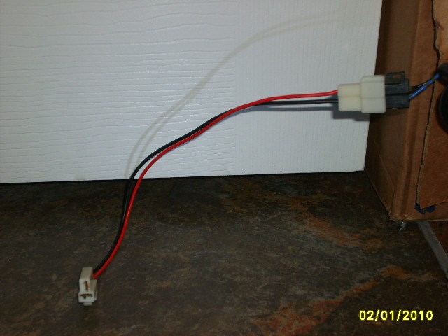
Last edited by a moderator:
road runner
Well-known member
RZ350I was giving this idea some more thought and decided to search through my electrical parts bins and found this. It’s a female to male extension harness that perfectly matches the fan connector. All I would need to do is cut the ground wire, solder/splice some extra length of wire onto each cut ground and add ring terminals to effectively do what road runner states above. It doesn’t help S6, but there’s a couple of ways to deal with that one (maybe that HID upgrade Fred mentioned :yahoo: ).Here's an idea.
Now, if I could just remember where I bought it, I could go get a bunch more.
That would work the nuts. The hot lead would just go to the fan, and the grnd would get cut in the middle. Put an eyelet on each grnd wire, and run them to the frame. One end would grnd the S4 spider, and the other would grnd the fan to the frame. It would do exactly what I was talking about, and would be a plug and play deal. I never thought of an extension harness, VERY nice idea. Now all we need is an extension harness for the headlight plugs and we are in business.
Good thinkin
A.C.
It seems that 3-blade female headlight connector is pretty common, but the male spade half is usually the bulb itself. Perhaps someone already makes one though. Has anyone seen one somewhere? Maybe a headlight relocation kit for a pickup snowplow or something?RZ350I was giving this idea some more thought and decided to search through my electrical parts bins and found this. It’s a female to male extension harness that perfectly matches the fan connector. All I would need to do is cut the ground wire, solder/splice some extra length of wire onto each cut ground and add ring terminals to effectively do what road runner states above. It doesn’t help S6, but there’s a couple of ways to deal with that one (maybe that HID upgrade Fred mentioned :yahoo: ).Here's an idea.
Now, if I could just remember where I bought it, I could go get a bunch more.
That would work the nuts. The hot lead would just go to the fan, and the grnd would get cut in the middle. Put an eyelet on each grnd wire, and run them to the frame. One end would grnd the S4 spider, and the other would grnd the fan to the frame. It would do exactly what I was talking about, and would be a plug and play deal. I never thought of an extension harness, VERY nice idea. Now all we need is an extension harness for the headlight plugs and we are in business.
Good thinkin
A.C.
S76
Well-known member
Your making this to complicated. Just cut, strip, solder, and add a few ground wires and your done. If you can't solder or don't have the equipment just pick up a rock and throw it. You are bound to hit someone who can.
Throw em a few bucks and just get it done.
Throw em a few bucks and just get it done.
Eastern Beaver has some stuff that might work, including the male spade plug, and it looks like the whole headlight circuit can be isolated via relays, if desired. Maybe a custom kit could even be built from his harness.It seems that 3-blade female headlight connector is pretty common, but the male spade half is usually the bulb itself. Perhaps someone already makes one though. Has anyone seen one somewhere? Maybe a headlight relocation kit for a pickup snowplow or something?
Click the linky
road runner
Well-known member
It's to late for me. I already cut and soldered. Just trying to come up with an easy way to fix this without cutting the harness or soldering. For those who can't or do not want to alter it.Your making this to complicated. Just cut, strip, solder, and add a few ground wires and your done. If you can't solder or don't have the equipment just pick up a rock and throw it. You are bound to hit someone who can.
Throw em a few bucks and just get it done.
JamesK
Got to ride
Are any of you guys employed by NASA .
I agree with Bob, just do the spiders directly, since if your concern is messing with the harness IMHO from Yamaha's point of view you'd still be altering the harness. I think as branmfrank pointed out, any claims Yamaha might have about this particular case of altering the harness to fix this kind of serious problem would be easily dismissed by a judge once this discussion thread was made available...
.I agree with Bob, just do the spiders directly, since if your concern is messing with the harness IMHO from Yamaha's point of view you'd still be altering the harness. I think as branmfrank pointed out, any claims Yamaha might have about this particular case of altering the harness to fix this kind of serious problem would be easily dismissed by a judge once this discussion thread was made available...
Your making this to complicated. Just cut, strip, solder, and add a few ground wires and your done. If you can't solder or don't have the equipment just pick up a rock and throw it. You are bound to hit someone who can.
Throw em a few bucks and just get it done.
:lol: +1
Yes - I think its great to give people alternatives to best suit their own situation.It's to late for me. I already cut and soldered. Just trying to come up with an easy way to fix this without cutting the harness or soldering. For those who can't or do not want to alter it.Your making this to complicated. Just cut, strip, solder, and add a few ground wires and your done. If you can't solder or don't have the equipment just pick up a rock and throw it. You are bound to hit someone who can.
Throw em a few bucks and just get it done.
Thanks. Looks like Jim sells all the parts needed to make a headlight Y-harness and you don't need a special crimper since it's already done for you. Link to individual partsEastern Beaver has some stuff that might work, including the male spade plug, and it looks like the whole headlight circuit can be isolated via relays, if desired. Maybe a custom kit could even be built from his harness.It seems that 3-blade female headlight connector is pretty common, but the male spade half is usually the bulb itself. Perhaps someone already makes one though. Has anyone seen one somewhere? Maybe a headlight relocation kit for a pickup snowplow or something?
Click the linky
Brodie - it looks like you have another choice for a complete plug-n-play kit. Will have to consider the ramifications of adding another potential failure point in this vital component though. At least there are two lights having separate wiring where the extra connections are being added.
I HAVE MY PLAN OF ACTION...
After researching, reading prior posts here, and giving this a bunch of thought, I feel I have a solution for setting my mind at ease about this problem. I hope others will benefit from all our work. Hopefully, Yamaha will intervene before I actually get through all 3 steps.
ROOT CAUSE: To me, it is obvious what the problem is here. The downstream ground spiders are simply getting overloaded. The wiring table shows which ones are worse off than the others (see Rev 04 in reply 287). Over time, a little corrosion pushes the overloaded terminals beyond their limits (in a degraded state) and things melt down.
A CAUTION: I don’t plan to do anything with spiders S2 or S5 (other than applying a little dielectric grease is prevent corrosion when accessible) since some wires in there are part of closed loop control circuits with isolated grounds. Since I don’t fully understand the logic inside those “black boxes” (the controllers), I don’t feel it’s necessary to mess with them and risk tampering with a feedback signal that could ultimately lead to safety issues someday. I also believe they are carrying much less current than the rest of the ground spiders so they are of no real threat of failure.
PLAN OF ACTION: Remember, this is my plan, based on the supplies I have at my disposal, my remaining YES warranty, and the current condition of my bike (low mileage). In general, applying dielectic grease to any connection on a bike is a good prevention against future corrosion.
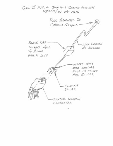
Step 1: Build one “5-INTO-1” repair spider connector as shown below and install it when I lift the tank to replace spark plugs. I just happen to have a spare spider and cap from the damaged portion of the front cowling harness so I can prepare the spider with ground lead prior to tearing into the bike. It wouldn’t take long to make one once the bike is apart though. I will not know exactly where to ground it on the chassis until I open it up, so I will solder on a long length of wire so I can cut-to-fit and crimp the ring terminal during installation. I’m in need of a spark plug change in the very near future so this will be an opportune time to do this step. This extra ground wire helps reduce the current flowing through spider S4-Pin3, the actual battery ground, where I believe the true trouble lies. This will eliminate a majority of the meltdown risk.
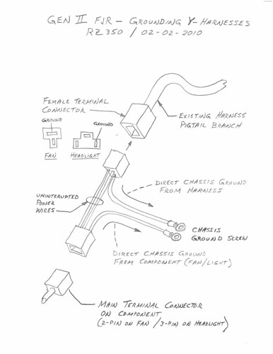
Step 2: Build two Y-connectors for the radiator fan motors (see below). I think this is important if you sit in traffic a lot and your fans come on often. These could also be prepared ahead of time, and be available when I’m ready to pull the side panels. As agreed upon by several forum members, they effectively will take the fan motor current (10A) completely out of the original ground loop AND add 2 additional ground paths to S4. At this time, I could remove the grounding spider wire installed in Step 1 since it is now redundant.
Step 3: If Yamaha has still not intervened with a factory fix to my liking, I will buy the necessary parts to build a similar Y-harness for each headlight. Like the fans, it will remove the headlight current from the original ground circuit (another 10A) and provide two additional ground paths for the front cowling harness (one each for S7 and S8). Even though an extra connection is added to each headlight creating another possible failure point, I feel the risk of BOTH lights going out at the same time is relatively low, therefore not a concern to me.
With all this done, I doubt there will ever be another issue with the grounding system. Good luck in fixing your bike.
Now - it’s time for me to do some riding...
After researching, reading prior posts here, and giving this a bunch of thought, I feel I have a solution for setting my mind at ease about this problem. I hope others will benefit from all our work. Hopefully, Yamaha will intervene before I actually get through all 3 steps.
ROOT CAUSE: To me, it is obvious what the problem is here. The downstream ground spiders are simply getting overloaded. The wiring table shows which ones are worse off than the others (see Rev 04 in reply 287). Over time, a little corrosion pushes the overloaded terminals beyond their limits (in a degraded state) and things melt down.
A CAUTION: I don’t plan to do anything with spiders S2 or S5 (other than applying a little dielectric grease is prevent corrosion when accessible) since some wires in there are part of closed loop control circuits with isolated grounds. Since I don’t fully understand the logic inside those “black boxes” (the controllers), I don’t feel it’s necessary to mess with them and risk tampering with a feedback signal that could ultimately lead to safety issues someday. I also believe they are carrying much less current than the rest of the ground spiders so they are of no real threat of failure.
PLAN OF ACTION: Remember, this is my plan, based on the supplies I have at my disposal, my remaining YES warranty, and the current condition of my bike (low mileage). In general, applying dielectic grease to any connection on a bike is a good prevention against future corrosion.
Step 1: Build one “5-INTO-1” repair spider connector as shown below and install it when I lift the tank to replace spark plugs. I just happen to have a spare spider and cap from the damaged portion of the front cowling harness so I can prepare the spider with ground lead prior to tearing into the bike. It wouldn’t take long to make one once the bike is apart though. I will not know exactly where to ground it on the chassis until I open it up, so I will solder on a long length of wire so I can cut-to-fit and crimp the ring terminal during installation. I’m in need of a spark plug change in the very near future so this will be an opportune time to do this step. This extra ground wire helps reduce the current flowing through spider S4-Pin3, the actual battery ground, where I believe the true trouble lies. This will eliminate a majority of the meltdown risk.
Step 2: Build two Y-connectors for the radiator fan motors (see below). I think this is important if you sit in traffic a lot and your fans come on often. These could also be prepared ahead of time, and be available when I’m ready to pull the side panels. As agreed upon by several forum members, they effectively will take the fan motor current (10A) completely out of the original ground loop AND add 2 additional ground paths to S4. At this time, I could remove the grounding spider wire installed in Step 1 since it is now redundant.
Step 3: If Yamaha has still not intervened with a factory fix to my liking, I will buy the necessary parts to build a similar Y-harness for each headlight. Like the fans, it will remove the headlight current from the original ground circuit (another 10A) and provide two additional ground paths for the front cowling harness (one each for S7 and S8). Even though an extra connection is added to each headlight creating another possible failure point, I feel the risk of BOTH lights going out at the same time is relatively low, therefore not a concern to me.
With all this done, I doubt there will ever be another issue with the grounding system. Good luck in fixing your bike.
Now - it’s time for me to do some riding...
Last edited by a moderator:
- Status
- Not open for further replies.
Similar threads
- Replies
- 8
- Views
- 943
- Replies
- 1
- Views
- 805
- Replies
- 0
- Views
- 564