I HAVE MY PLAN OF ACTION...
After researching, reading prior posts here, and giving this a bunch of thought, I feel I have a solution for setting my mind at ease about this problem. I hope others will benefit from all our work. Hopefully, Yamaha will intervene before I actually get through all 3 steps.
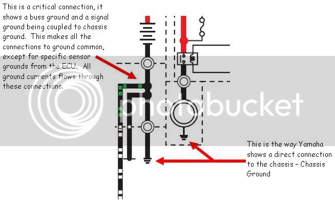
ROOT CAUSE: To me, it is obvious what the problem is here. The downstream ground spiders are simply getting overloaded. The wiring table shows which ones are worse off than the others (see Rev 04 in reply 287). Over time, a little corrosion pushes the overloaded terminals beyond their limits (in a degraded state) and things melt down.
A CAUTION: I don’t plan to do anything with spiders S2 or S5 (other than applying a little dielectric grease is prevent corrosion when accessible) since some wires in there are part of closed loop control circuits with isolated grounds. Since I don’t fully understand the logic inside those “black boxes” (the controllers), I don’t feel it’s necessary to mess with them and risk tampering with a feedback signal that could ultimately lead to safety issues someday. I also believe they are carrying much less current than the rest of the ground spiders so they are of no real threat of failure.
PLAN OF ACTION: Remember, this is my plan, based on the supplies I have at my disposal, my remaining YES warranty, and the current condition of my bike (low mileage). In general, applying dielectic grease to any connection on a bike is a good prevention against future corrosion.
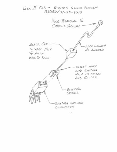
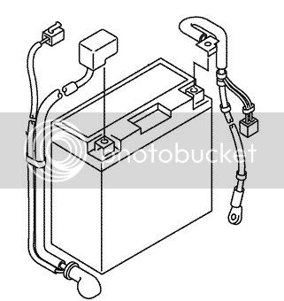
Step 1: Build one “5-INTO-1” repair spider connector as shown below and install it when I lift the tank to replace spark plugs. I just happen to have a spare spider and cap from the damaged portion of the front cowling harness so I can prepare the spider with ground lead prior to tearing into the bike. It wouldn’t take long to make one once the bike is apart though. I will not know exactly where to ground it on the chassis until I open it up, so I will solder on a long length of wire so I can cut-to-fit and crimp the ring terminal during installation. I’m in need of a spark plug change in the very near future so this will be an opportune time to do this step. This extra ground wire helps reduce the current flowing through spider S4-Pin3, the actual battery ground, where I believe the true trouble lies. This will eliminate a majority of the meltdown risk.
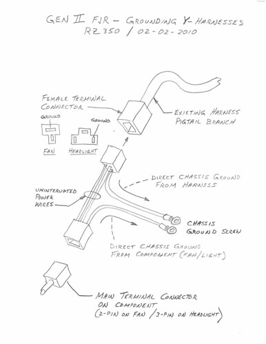
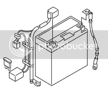
Step 2: Build two Y-connectors for the radiator fan motors (see below). I think this is important if you sit in traffic a lot and your fans come on often. These could also be prepared ahead of time, and be available when I’m ready to pull the side panels. As agreed upon by several forum members, they effectively will take the fan motor current (10A) completely out of the original ground loop AND add 2 additional ground paths to S4. At this time, I could remove the grounding spider wire installed in Step 1 since it is now redundant.
Step 3: If Yamaha has still not intervened with a factory fix to my liking, I will buy the necessary parts to build a similar Y-harness for each headlight. Like the fans, it will remove the headlight current from the original ground circuit (another 10A) and provide two additional ground paths for the front cowling harness (one each for S7 and S8). Even though an extra connection is added to each headlight creating another possible failure point, I feel the risk of BOTH lights going out at the same time is relatively low, therefore not a concern to me.
With all this done, I doubt there will ever be another issue with the grounding system. Good luck in fixing your bike.
Now - it’s time for me to do some riding...