Here's an idea.
")
Maybe good , maybe not so good. Check it out and let me know. So maybe if someone didn't want to mess with the spiders they could remove the original grnd wires from the fans, ground the fans to the chassis by making up 2 new wires, then hook the original 2 fan grnd wires (previously removed) to the chassis. This will take the fans out of the equation and add 2 chassis grnd wires to the S4 (BLACK WIDOW) spider without modifying it.
Then they could tap into the Acc. jack or the glove box grnd wire or both, then run them to chassis also. This will add 1or 2 grnd wires to the S6 spider, and should take care of the headlights and shield drive.
I think that would take care of the overload situation. Of coarse they would still have to clean, and grease all the spiders once a year.
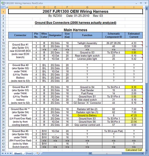
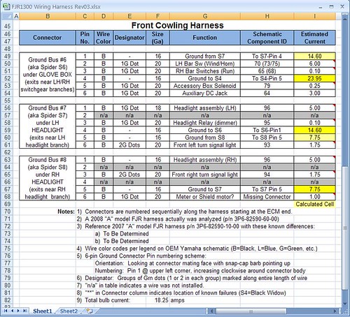
I couldn't have come up with this idea if not for RZ350s excellent chart of what goes where. Thanks RZ
More food for thought; A.C.