A Bunch Of Farkles

Yamaha FJR Motorcycle Forum

Help Support Yamaha FJR Motorcycle Forum:

This site may earn a commission from merchant affiliate links, including eBay, Amazon, and others.

BrunDog

Well-known member
Joined
Jun 14, 2005
Messages
1,223
Reaction score
1
Location
West Palm Beach, FL
I got done a few electrical farkles I've been working on.

Part 1:

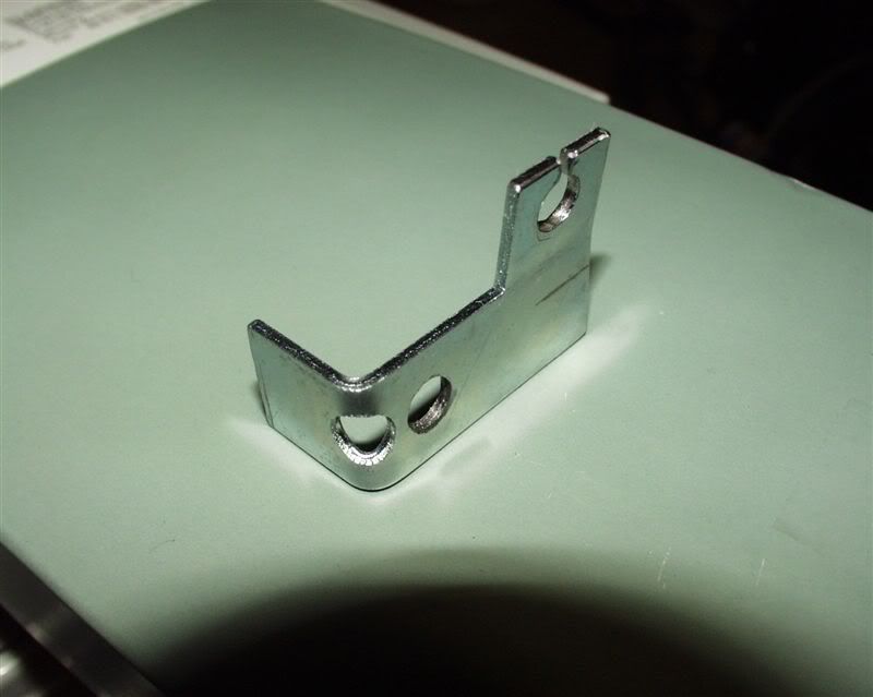
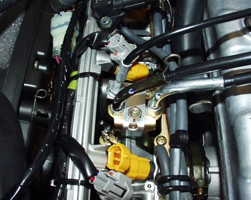
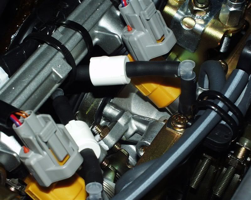
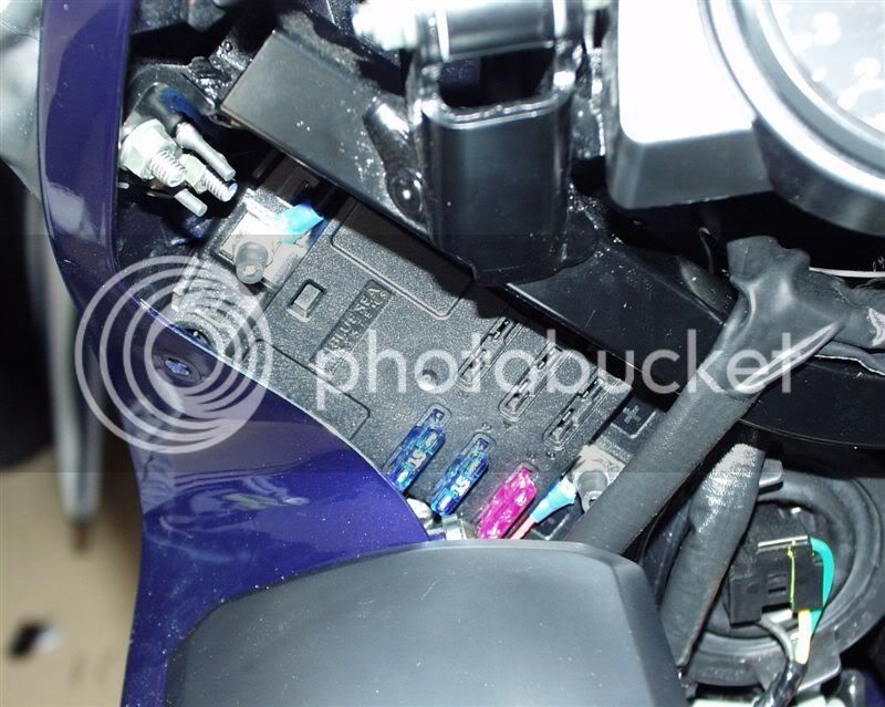
1. Fuseblock. I really wanted to use a BlueSea block that I had bought, ($30) but struggled to find a good spot. What is really nice about this block is that it has both ground and +12V terminals, and it is built like a brick shithouse. I didn't want to put it behind the tank or in the tail. I noticed that I could put it under and forward of gauges but it would be difficult to service it there. Then I found a nice spot behind the left upper corner panel:

P8071618.jpg


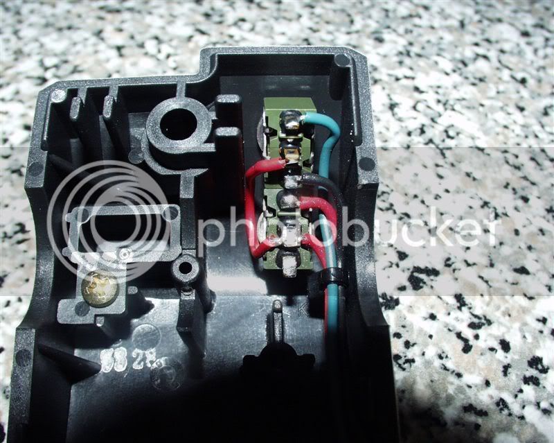
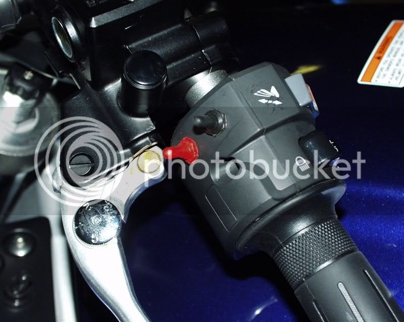
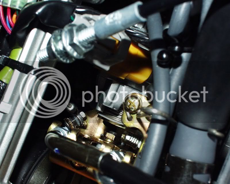
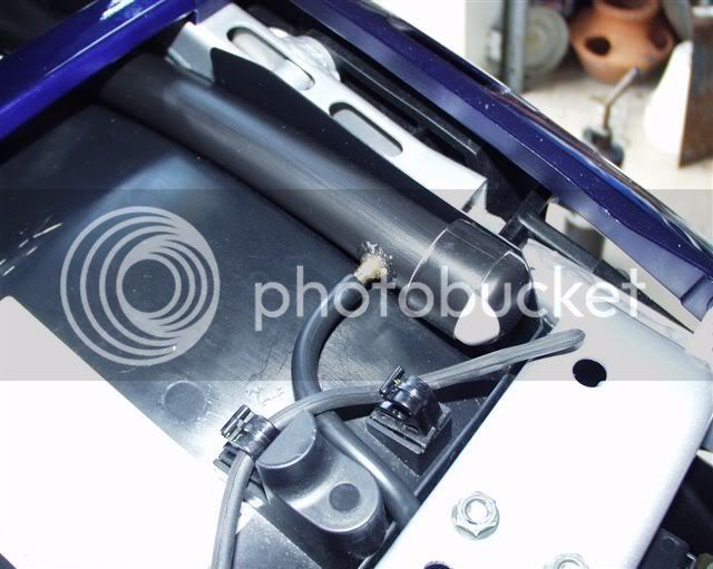
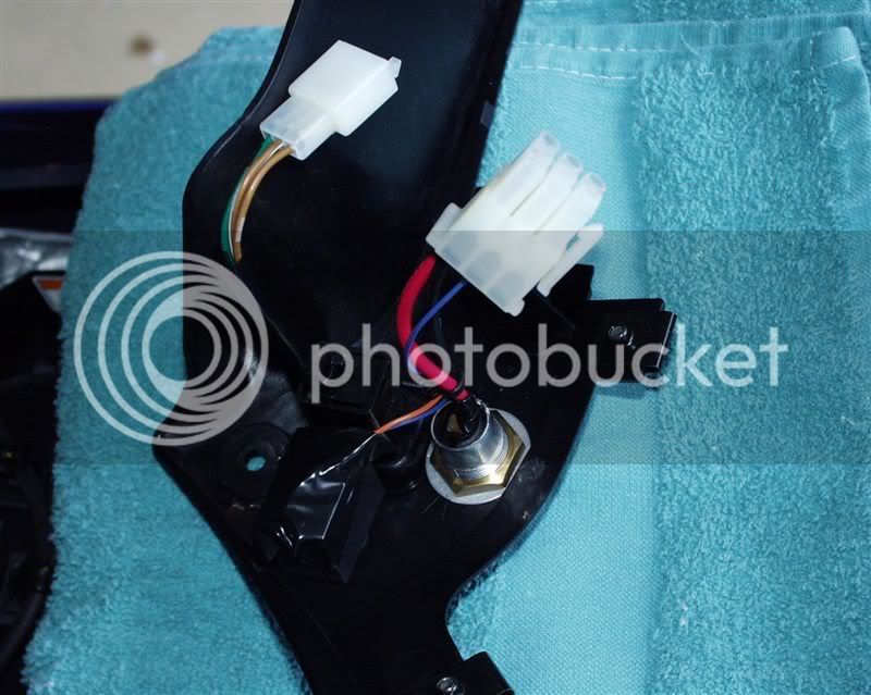
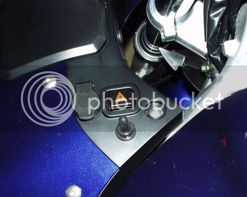
2. Powerlet / fan switch. I added the powerlet and a switch to command the radiator fan on. I live in South Florida, so I would like the option of turning the fan on on purpose to preemptively cool the motor in idle situations. The switch I selected is waterproof (splashproof). To make that even better, I put on a rubber boot. The switch grounds the ECU side of the relay. I noticed that the hazard had a connector on it for ease of removal, so I added one also:

P8071619.jpg


P8071630.jpg


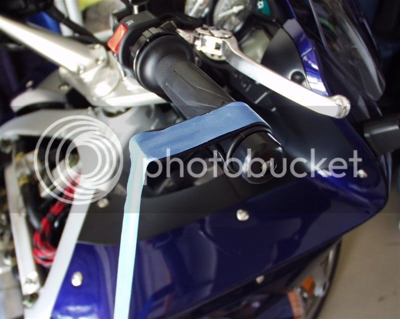
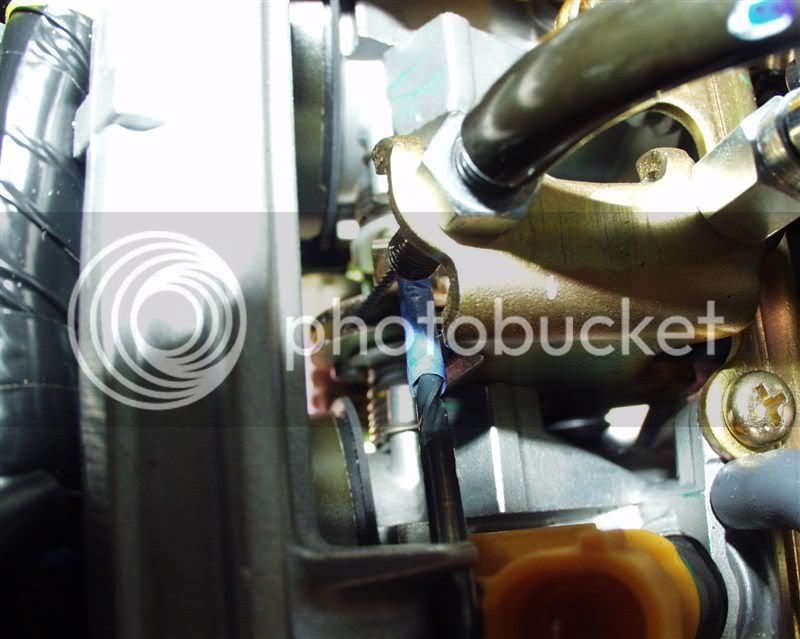
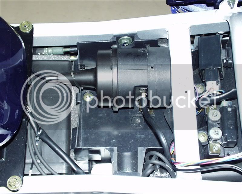
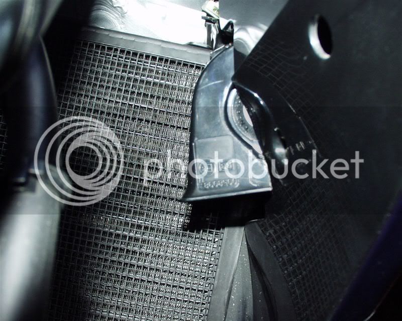
3. Magnums. If you read another post you would know the process I went through to decide how best to connect these. Ultimately the 2V drop across the factory wiring and uncertainty of current capacity of the switch led me to add a relay and 12 AWG wire to my fuseblock. Now my voltage drop is <0.5 V. The horns are a tight fit but I managed to add them without modifying the bike's plastic and using the stock brackets. The trick to provide enough fork clearance was to trim the unnecessary part of the trumpet plastic:

P8071632.jpg


Last edited by a moderator:
Part 2:

4. Audiovox CC. Thanks to so many guys who blazed this trail and took the time to write about it. Here is how I did mine.

First, I personally did not want alot of extra hardware hanging off my handlebars. Second, I was unsure that the stock membrane pad could not be made entirely waterproof. Third, I didn't really feel like making a fancy bracket to position it. Fourth, I wanted to keep my mirror hole free for something else someday. So, I put two splashproof switches in the left handlebar housing. Then I added rubber boots to protect them further. A firehose couldn't affect these things. The lower (red) is a two position switch used for ON/OFF. The upper (black) is a three position momentary for SET/COAST and ACCEL/RESUME. The wires run through the stock harness to keep it clean:

P7031429.jpg


P8071626.jpg


The first trick was to drill the tab. I did this whole install without removing the fuel rail, but in hindsight, I should have. I used my crampbuster and tape to hold the throttle in place:

P7161463.jpg


Then I used an extra long 1/8" bit through the #3 injector mount to the tang. The blue tape was to protect the cable in case something moved:

P7161461.jpg


Here are two pictures of my tang assembly. I did not want to use beaded chain so I didn't. The assembly is a #4 BHSCS (button-head socket cap screw), nut with star lock washer, two nylon collar spacers sandwiching a nylon spacer, and another nut. The last nut was supposed to be a locking nylon loaded type but I could not get any torque on it given the tight quarters. Around the nylon spacer is the small eyelet provided with the CC kit. The button head screw has no interference with the cable and I did NOT have to bend the tang:

P7171470.jpg


P7171473.jpg


Last edited by a moderator:
Part 3:

I could not find an adequate way to mount the cable with the stock products, so I made my own bracket:

P7171476.jpg


And mounted it by drilling a hole in the stock cable mount bracket between the cables:

P7191480.jpg


I added small, high temperature, positive spring check valves on each vacuum nipple as close to the nipple as I could. After these, the 1/4" OD hose reduces down to 1/8" OD:

P7301564.jpg


EDIT: Ignore this line, see below: I made a small reservoir with flexible 3/4" OD PVC pipe. I glued the four 1/16" ID nipples for the four vacuum tubes and a larger one for the servo:

EDIT: Ignore this line, see below: Here it is mounted. It fits over the ECU connector and runs to the top of the back fender, just under the front seat back crossbar:

And here is the servo mounted. I put it in the stock tool tray without removing the tray and it fit nicely. I did need to remove a little plastic from the bottom of the seat, but this was no issue. You can see the tubes running to the reservoir here too. The multi color cable is just pulled out of the way for the photo. When I ran the wiring, I added this 6 conductor cable for future electric items:

P8071621.jpg


By the way, I used a lot of this loom for all the wiring, and I really like this stuff. It is PVC, high temp, has polyester threads in it, and comes flat with an adhesive strip along one edge. You can cut it to any size, and put it on a wire that is already terminated on the ends or just make it into a tube and use it like a regular loom, too. It is hard to identify compared to the bike's existing loom. Get it at McMaster and look for "Vinyl-Coated Polyester Wrap-Around Sleeving":

P8071620.jpg


5. Hyperlites. I put the dual function dual 16 LED set on. I forgot to take a picture, but I put them under the tail overhang. While this does not provide the best separation, the wiring rins right up behing the modules into the tail where the brakelight wires are easily accessed. Even though they are near the stock lights, you can't miss these - they are bright and they flash.

6. Barbarian jumper. You all know what this is about.

Well, that's it for now. I don't think I will be adding too much in the near future, now that I have everything done wrt electrics and protection items that I wanted to. I think I'll just ride it.

-BD

 
Last edited by a moderator:
Nice work BD...and the pics also...I want to mount a garage opener remote using the small weather proof toggle switches you have mounted for you cruise. The unit I have is only small about the size of a large coin but I haven't pulled it apart yet. Are the Electric clusters easy to pull apart in that there are no little springs that go "Bing" and never found again?

 
Last edited by a moderator:
Yeah, the front black panels are quite easy to remove. Go to HERE for more details.

I did make a mistake of test riding my bike with the upper right panel screw (button head) slightly screwed into the clip and it vibrated itself out and buh-bye!!

Anyone know where I can get a replacement?

-BD

 
BrunDog, great post. Oviously well conceived and impemented. Thanks for the insight and sharing your skills and knowledge.

Don

 
I got the switches (and other electronics, always) from Digi-Key.

The miniature switches in the housing - SET/COAST/ACCEL/RESUME switch is 360-1143-ND ($7.50) and the ON/OFF switch is 360-1140-ND ($6.06):

Hit me!

The boots - Black 335-1003 and red 335-1002 ($4.56 ea):

Hit me!

The radiator fan switch and boot are different, let me know if you want it.

*** I NOTICED A BIG MISTAKE I MADE ON THE ABOVE RESERVOIR! ***

The location I put it seemed cool at first, but I realized that I screwed the pooch by putting it there. Reason: that is the path air flows in to the intake! Dumbass... I don't know if it was really affecting performance, but I am not willing to risk it. So I moved the reservoir to the back, pictures to follow.

-BD

 
Last edited by a moderator:
Yo Brun,

Can you post a schematic for you Cruise Control switches? That is what I was looking to do buy understanding the wiring is holding me back. Thanks.

Tim

 
Ahhh, I am afraid that would take a bit of time... Here is the verbal version.

+12V (from fuse block) to ON/OFF switch , other side to BROWN wire of CC and also to SET/ACCEL momentary switch center pole (provides a safety in that if the ON/OFF switch is off, the SET/ACCEL switch can't pass the +12V signal to the servo instructing it to change speed). Other sides of SET/ACCEL switch to YELLOW wire and GREEN wire of cruise control (check which is which, I don't recall).

The RED wire of the servo also goes to the same +12V above.

The PURPLE to the BRAKE +12V, which is a yellow wire heading back toward the taillights. The BLUE wire to the ignition coil primary (tach). I connected mine to the GRAY wire at the ECU. BLACK of course goes to ground. You can use the black in the taillights, too).

Good luck. And get a bike schematic and a VOM to ensure you pick the right wires!

-BD

 
Don't mean to perpetuate my own post, but is the change I made to my reservoir. It ended up being bigger and out of the airflow of my intake path.

I put a longer piece of flexible PVC with capped ends (like above) and a barbed nipple along the left side of the rear fender under the seat:

P8131693.jpg


-BD

 
Last edited by a moderator:
great post Brun dog. You have convinced me that my vista cruise is good enough for me! I just don't want to do all that stuff...maybe I'm just scared :huh: :eek:

 
Ancient Thread Revival.

After seeing some recent posts for the "flash to pass" rocker switch on the left handlebar control pod, I did some looking on the Digikey web site. I think I'm going to order P/N SW340-ND, which is a panel rocker switch that is momentary-off-momentary SPDT. This should be perfect for the "Accel-Coast" function of the Audiovox CC. Cost is $1.51 each. I don't know if the tabs can be bent/trimmed enough to fit, though. I'll likely go with the toggle type for the "on-off" function. I may tamper with the "on" led and see if it's feasible to drill a hole on the driver's side of the control pod for it.

Pepperell

 
I just did a major Farkle order yesterday:

Audio-Vox Cruise

PR2's

Mojo-Blocks for my HF Tire changer

Heated Grips (I bought the ATV version and will putting them over the stock grips with Grip Puppies over them, works very well on my Wee)

Heat-Troller for the grips (this will be going in the left switch housing)

Dual Heat-Troller for my Gerbing jacket, gloves and heated insoles (not sure where I'll mount the knobs for these?)

Fuse box and wiring harnes from Eastern Beaver (probably put it under the seat)

Stebil Horn (location TBD)

Looking forward to getting it all in then starting the teardown and install process.

This thread will be a big help!!!

 
Last edited by a moderator:
Wow. I haven't been active on the forum for a while - life's priorities have kind of taken over. Also been busy learning to fly and just wrapping up IFR...

Popped on to see what was new, and I saw this old post on the recent list. Glad to see people still getting ideas from it, but my heart dropped remembering two fallen forum brothers. Orangevale and TWN: your memory lives on here. You are truly missed.

-BD


Latest posts

Top