Could that have been due to the radiator fan kicking on? That sucker draws a mean load.I was just out on a 1.5 week trip/tour and started noticing that the voltage on the Datel was sometimes showing around 13.8V, this is with minimal loads, running during the day.
You are using an out of date browser. It may not display this or other websites correctly.
You should upgrade or use an alternative browser.
You should upgrade or use an alternative browser.
KrZy8 Gen2 - Charging Circuit
- Thread starter dcarver
- Start date


Help Support Yamaha FJR Motorcycle Forum:
This site may earn a commission from merchant affiliate
links, including eBay, Amazon, and others.
SkooterG
Purveyor of Crooked Facts
Don't forget about heat. At start up, my Gen I can read 14.1+ and an hour or so later when nice and hot can go down to 13.9.Could that have been due to the radiator fan kicking on? That sucker draws a mean load.I was just out on a 1.5 week trip/tour and started noticing that the voltage on the Datel was sometimes showing around 13.8V, this is with minimal loads, running during the day.
JamesK
Got to ride
Fred, that's a good point, but I made sure that the fans were not running both because the temp gauge was showing 5 bars or less (on the Gen II the fans kick in at 7 bars) and by physically checking/listening for the fans. Also, after fiddling with the connector the problem disappeared.Could that have been due to the radiator fan kicking on? That sucker draws a mean load.I was just out on a 1.5 week trip/tour and started noticing that the voltage on the Datel was sometimes showing around 13.8V, this is with minimal loads, running during the day.
Last edited by a moderator:
JamesK
Got to ride
Scooter, that's a good point too, but that is not the case at least with the new FH020AA units, which I happen to be running. I know the Gen I uses the FH001A R/R which is a shunts excess power, but the FH020A turns off the circuit so does not over heat or change characteristics (at least not as much)...Don't forget about heat. At start up, my Gen I can read 14.1+ and an hour or so later when nice and hot can go down to 13.9.Could that have been due to the radiator fan kicking on? That sucker draws a mean load.I was just out on a 1.5 week trip/tour and started noticing that the voltage on the Datel was sometimes showing around 13.8V, this is with minimal loads, running during the day.
rfulcher
Well-known member
Add another success to the list. I installed the R/R harness from Jack at roadstercycle.com and went from 3.7-3.8 volts to 14.1 occasionally 14.2 volts. I am a happy camper. :yahoo:
RadioHowie
I Miss Beemerdons!
A 10.5 volt increase???? :huh: :blink: :dribble:Add another success to the list. I installed the R/R harness from Jack at roadstercycle.com and went from 3.7-3.8 volts to 14.1 occasionally 14.2 volts. I am a happy camper. :yahoo:
JamesK
Got to ride
I was waiting to see which wise guy would pick up on that typo :lol:A 10.5 volt increase???? :huh: :blink: :dribble:Add another success to the list. I installed the R/R harness from Jack at roadstercycle.com and went from 3.7-3.8 volts to 14.1 occasionally 14.2 volts. I am a happy camper. :yahoo:
rfulcher
Well-known member
Well it felt like a 10.5 volt increase.I was waiting to see which wise guy would pick up on that typo :lol:A 10.5 volt increase???? :huh: :blink: :dribble:Add another success to the list. I installed the R/R harness from Jack at roadstercycle.com and went from 3.7-3.8 volts to 14.1 occasionally 14.2 volts. I am a happy camper. :yahoo:

ToyQuest
Well-known member
Add one more bike to the upgrade success group. I updated both wiring and the R/R. I went a little different route wiring selection wise. I used 8ga marine grade super flex wire rather than the zip type 10ga that Jack provides. Besides being thinned, it seemed to have a little lower resistance rating than the general zip type wire. Additionally, I used a 50 amp auto reset circuit breaker rather than the 30 amp to align with the larger gauge wire.
I gained ~0.5V from the original wiring harness and original R/R to the new setup I went from 13.8V max with only Starcom / V1 additional load at 4500 to 14.3V at 4500. Here are the pics showing the Fluke, the Datel, the tack, the temperature gauge.
No fans, idling
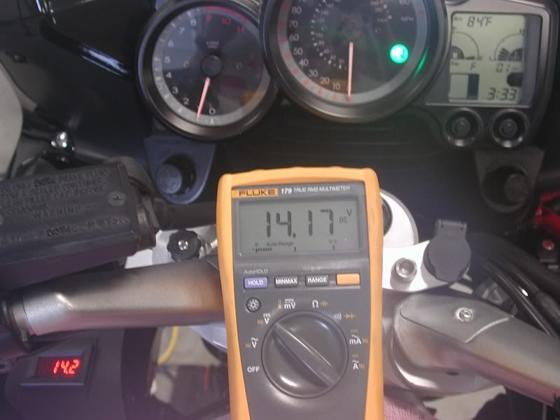
No fans, 4500 rpm
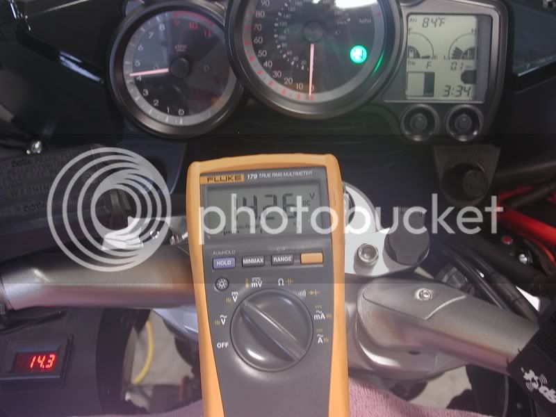
Fans on, idling
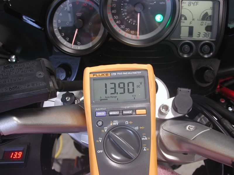
Fans on, 4500 rpm
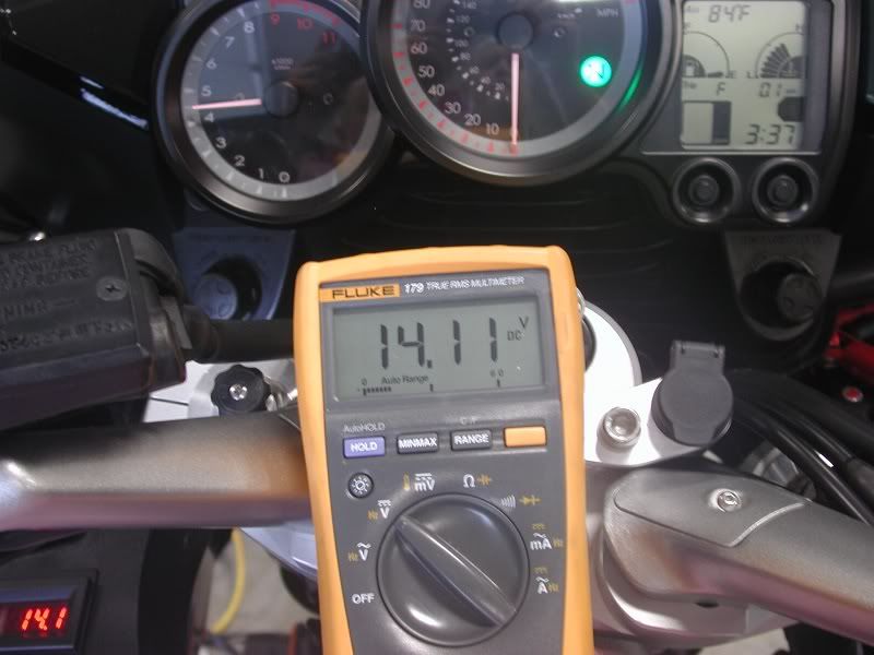
Road testing with the Starcon / V1 / Garmin GPS / MP3 player, it cruses at a rock solid 14.2V.
Props to all for the research and info sharing
I gained ~0.5V from the original wiring harness and original R/R to the new setup I went from 13.8V max with only Starcom / V1 additional load at 4500 to 14.3V at 4500. Here are the pics showing the Fluke, the Datel, the tack, the temperature gauge.
No fans, idling
No fans, 4500 rpm
Fans on, idling
Fans on, 4500 rpm
Road testing with the Starcon / V1 / Garmin GPS / MP3 player, it cruses at a rock solid 14.2V.
Props to all for the research and info sharing
dcarver
Well-known member
Excellent results, TQ!
May I ask where you sourced the 8ga marine grade super flex wire?
RFulcher - man, it DOES feel good, eh?
JamesK - interesting to note you had to 'set' or 'wiggle' the connector after some runtime to get back to 'good' values. I DID find the major voltage drop, e.g. resistance, at the positive wire of the RR output connector, adding credence to your point. I've not had the same result, but then again all of my loads have taken a dump.. The Soltek lights broke the front stay, again, so they are off, and I'm going to different lights. I will say that running a 90 watt heated jacket, high beams, etc. doesn't even phase the charging circuit. :lol:
Me thinks as time goes on, this thread will pick up post counts and maybe even be worthy of a 'pinned' thread..
Edit - post title changed
Last edited by a moderator:
JamesK
Got to ride
DC, IMHO this post is definitely worthy of a sticky, since it offers a great, economical and functional solution for every GenII FJR.
Since posting up my observations about the R/R terminal contacts I've seen this come and go maybe a couple of times, and it's annoying the crap out of me :angry2:
If when Bob (S76) ever replies about where he sourced his terminals and exactly what they are I will be looking to replace the Furukawa terminals.
@TQ I too am interested to find out what/where/how you got your wiring from, and what issues if any you experienced with fitting the 8ga into the Furukawa R/R connector/terminals.
Last edited by a moderator:
03HiYoSilver
Well-known member
This link may help:...If when Bob (S76) ever replies about where he sourced his terminals and exactly what they are I will be looking to replace the Furukawa terminals.
...
https://www.easternbeaver.com/Main/Elec__Products/Connectors/R_R_Connectors/r_r_connectors.html
dcarver
Well-known member
Those are 'stock'.. The other feller found some automotive connectors that fit..This link may help:...If when Bob (S76) ever replies about where he sourced his terminals and exactly what they are I will be looking to replace the Furukawa terminals.
...
https://www.easternbe...connectors.html
So... let me throw this out there:
(and don't crucify me if there actually is a good reason, 'cause I haven't thought this through fully)
Why do we need all of these quick disconnecty type of connectors in the charging system?
There are no routine maintenances that I am aware of that require you to disconnect the alternator from the R/R from the Battery. If you actually were changing one of these components, it's probably because it has failed. Right?
So, other than the battery terminals, why do we need these crappy connections? Hard-wire the sumbitch and be done with it!
ionbeam
2 FUN
On the + circuit you need to connect either a fuse or circuit breaker in series. While a straight connection is always the best sometimes the real potential (pun?) for fires and arc welding should be protected against. Plus, Yamaha makes available another terminal tie point at the starter relay before the R/R output finally meanders on up to the battery terminals.
Last edited by a moderator:
Yes, yes... understood. So, hard wire the circuit breaker.
I'm talking mostly about all of these unnecessary quick disconnects. Like we pull the system apart a lot or something?
I'm talking mostly about all of these unnecessary quick disconnects. Like we pull the system apart a lot or something?
dcarver
Well-known member
Fred, thought about doing during one low moment of frustration..
Me thinks it would be easy to take a stock terminal and solder both ends..
One to the wire, the other end to the RR output terminal.
Dremel off the stupid plastic around it first...
Clean, then seal it with rubberized electricians compound/tape.
Oh, fuses are for sissies!

Me thinks it would be easy to take a stock terminal and solder both ends..
One to the wire, the other end to the RR output terminal.
Dremel off the stupid plastic around it first...
Clean, then seal it with rubberized electricians compound/tape.
Oh, fuses are for sissies!
If one wanted to proceed in this direction, I would definitely plan on some kind of fusing or circuit breaker protection, somewhere in the line 'tween alternator and battery. Where exactly doesn't really matter much as the current goes in both directions (near the battery)., so maybe that end makes the most sense?
But for the remainder of these quick disconnect type plugs, why not just use butt splice crimps, then solder (with high temp solder) and use some good, self sealing, heat shrink tube insulation around each splice. This is a (very) low voltage application, so the insulation quality is not as important as the resistance of the splice joint.
But for the remainder of these quick disconnect type plugs, why not just use butt splice crimps, then solder (with high temp solder) and use some good, self sealing, heat shrink tube insulation around each splice. This is a (very) low voltage application, so the insulation quality is not as important as the resistance of the splice joint.
Last edited by a moderator:
ToyQuest
Well-known member
I purchased the 8/2 AWG that was thinned from "tinned_marine_wire" on ebay. I had bought other marine wire from him before. All top-shelf wire. Here is his current listing for 8/2 in Red/Yellow. https://www.ebay.com/itm/8-2-Gauge-AWG-Tinned-Duplex-Marine-Wire-Red-Yellow-PER-FOOT-/300739329679?pt=Boat_Parts_Accessories_Gear&hash=item460575fe8f When I just looked, I didn't see the Black//Red auction like what I have. I'm sure he'll post up more. If not just contact him directly.@TQ I too am interested to find out what/where/how you got your wiring from, and what issues if any you experienced with fitting the 8ga into the Furukawa R/R connector/terminals.
As for additional connectors/terminals, I just contacted Jack at https://www.roadstercycle.com/ and had him ship me an extra black connector and 6 extra terminals with his standard product offering. I wanted the spares to ensure that I had plenty to test/workout any fitment issues. BTW - He was great to work with.
Now for the fitting the 8ga into the standard terminal. It does take a little creativity but it can be easily accomplished. Naturally all of the 8ga strands will not fit into the terminal crimp. I did NOT remove any strands. I simply divided the strands into sections 1/6 left group, 2/3 center group, 1/6 right group (think crow's foot)
I took the center section of strands and crimped them into the terminal normally. That left the left group positioned left of the terminal crimp and the right group positioned right of the terminal crimp. I twisted and push both left and right sections against their respected outside edge of the crimp and solder it into a unified group.
The only fitment issue that you have to be careful to avoid is making the solder group thicker/higher than the terminal female housing. If it is higher it will not fit. If it is as wide as the female housing it will easily fit. Using this strategy, the solder up unit will be almost as wide as the female housing but no taller.
Sorry but I don't have a pic of a completed R/R terminal. Like S76, I used 3 small O-rings sourced from my local home improvement store to press into the connector block after assembly. These were 5/16OD x 3/16ID x /1/16. They stretched and fit perfectly into the connector opening. Make sure to put them on before you solder everything up
Hope that helpsLAF
Well-known member
All righty then.
I have read this and believe for sure I am afflicted.
I want the Marine wire and all the other parts!
However I am challenged and need help doing it. Anyone going to attempt this in a few hundred mile area from Harrisburg PA?
I will pay you, buy you the setup outright, just need some help. I am physically challenged to say the least.
I am on a 4 week West tour right now sitting in Salina KS at a KOA. Tomorrow is Denver. See post under Ride Reports.
So if anyone near Harrisburg is willing to do this and has the electrical know how, I will be home the end of the month.
I can order all parts while out on the road and ship them to you while I am gone so they are there.
Anyone interested in helping a gimp out? I am retired/disabled so I have every day open.
Similar threads
- Replies
- 2
- Views
- 508
- Replies
- 78
- Views
- 3K