Broken Penske Clevis.

Yamaha FJR Motorcycle Forum

Help Support Yamaha FJR Motorcycle Forum:

This site may earn a commission from merchant affiliate links, including eBay, Amazon, and others.
^^^^^^
I agree, Tom. The ...Clevis in post # 70 looks solid as a rock...Their transition radius will handle the loads with no problem at all.
So, at the next EOM are you going to bring your specialty tools and run a shock Clevis X-Ray clinic?
smile.png
Nah, he's just gonna use his thumb and call it good! X-Rays are dangerous Alan, are you kidding me? You could grow a 3rd eye from that stuff.

 
Last edited by a moderator:
^^^^^^
I agree, Tom. The ...Clevis in post # 70 looks solid as a rock...Their transition radius will handle the loads with no problem at all.
So, at the next EOM are you going to bring your specialty tools and run a shock Clevis X-Ray clinic? :)
Can't do that, Ionbeam. My machine and I would have to be registered in the state being that it puts out radiation but, I have all sorts of equipment that can detect even the tiniest crack in seconds. We'd have to remove the suspect clevis though. :yes:
 
^^^^^^
I agree, Tom. The ...Clevis in post # 70 looks solid as a rock...Their transition radius will handle the loads with no problem at all.
So, at the next EOM are you going to bring your specialty tools and run a shock Clevis X-Ray clinic?
smile.png
Can't do that, Ionbeam. My machine and I would have to be registered in the state being that it puts out radiation but, I have all sorts of equipment that can detect even the tiniest crack in seconds. We'd have to remove the suspect clevis though.
yes.gif
I'd just dye to know what you are thinking ;)

 
You folks might also want to look at the yoke design used on the Ohlins shock. I'm not aware of any failures with that shock. I've had 3 of the Ohlins for over 65000 miles and no problems.

 
Welding is out of the question. I suspect the part is made from 2024 high strength aluminum after looking at the failure photos. 2024 is not weldable. From Wiki:

Aluminum alloy 2024 is an aluminum alloy, with copper as the primary alloying element. It is used in applications requiring high strength to weight ratio, as well as good fatigue resistance. It is weldable only through friction welding, and has average machinability.

IMHO, It probably would be a good thing if the new part was made from steel.

 
Since the thread is about Penske breaks...here are some high res pictures of the two failures I had. (You can click on each for even higher resolution).

First is the most recent failure with the two pieces in the picture. Failure is on the side with the big hole just barely into the thread barrel.

MWK02721.jpg


MWK02721b.jpg


My first failure I could only find one piece. Seemed to break closer to the threads and, interestingly, the failure is on the small hole side much closer to the middle.

MWK02720.jpg


MWK02720b.jpg


My recollection is that I tried my leftover Wilbers on both of these items and after the 2nd I thought I needed to use a shouldered bolt. With failure on the opposite sides...I wonder a little if it was that.

Remember too that mileage on each of these before failure was somewhere between 0 and 20,000-30,000 miles on a well loaded rally bike with fuel cell, luggage, and my big ass.

 
Last edited by a moderator:
Ignacio, That's a classic picture of what happens. First, the fracture starts at the radius. Then moisture gets into the crack. Moisture in and of itself is not a problem because when it rains and the area is nice and clean you can ride in rain and get moisture in the crack but it'll be dry in no time at all. The problem starts when you have thick caked on mud thats found it's way into the crack and now the mud is wet and it stays wet All The Time!. That's why there's that big freakin' hole on the clevis and the piece that snapped off. If you mate them, they both have that hole at the same place. After 20-30K the muddy moisture in the crack had all the time in the world to corrode that huge hole and eventually it gave up the ghost. That's an awesome picture.

Moral of the story? Keep that undercarriage linkage area clean all the time, boys and girls... :)

Mine is 10 years old and my undercarriage looks like it just came off the showroom floor. :yes:

 
Last edited by a moderator:
I wonder if laying a TIG bead all the way around the base of the bolt would help to keep these things from breaking.

 
Last edited by a moderator:
You folks might also want to look at the yoke design used on the Ohlins shock. I'm not aware of any failures with that shock. I've had 3 of the Ohlins for over 65000 miles and no problems.
I've never heard of a case of the stock clevis breaking, and there are far more of those on the road than Penske or Ohlin shocks combined. As they say regarding bicycle frames... "Steel is real!"

PS - Here's a list of all of the metal elements that a magnet will not stick to:

Everything (except iron)

 
Last edited by a moderator:
Great images Ignacio, thanks.

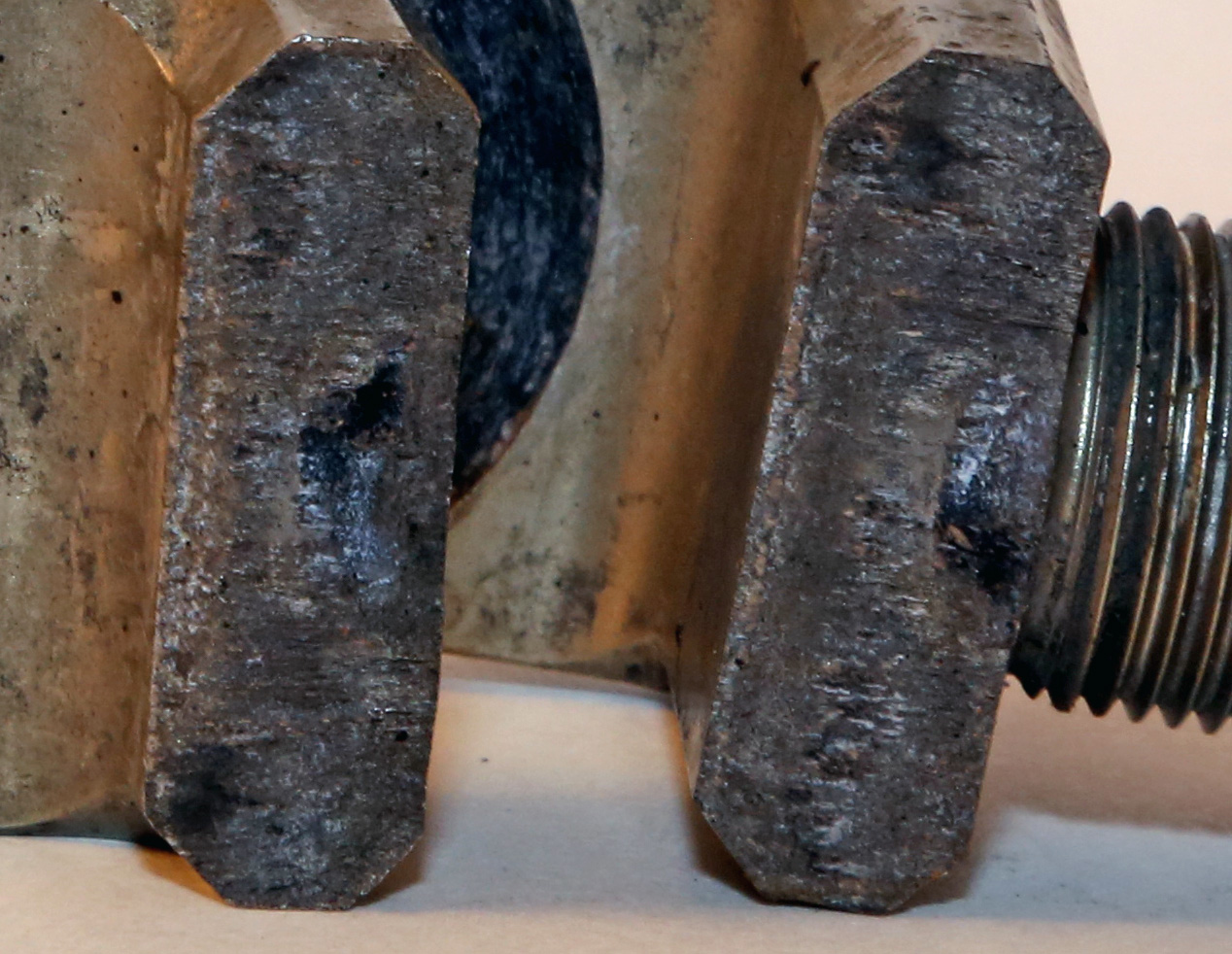
By my partially trained eye, your second failed clevis appears to confirm what we've suspected: crack initiation at the intersection of the clevis and base of the threaded rod. Then the crack propagated with slow movement until about 15-20% of the cross section had cracked, and then it proceeded to a complete failure of the remaining area in relatively quick fashion (perhaps upon a single, sudden load).

Your first clevis failure shows similar by my partially trained eye, but appears to have took longer to fail. It appears the crack also initiated at the intersection of the clevis and base of the threaded rod, then proceeded slowly over time to about 40-50% of the cross section, then the failure completed in quick fashion. It appears this clevis is steel (rusting iron), or it was stored [after failure] near iron-based metal?

It also appears that the raw stock that the second failed clevis was made from (appears some kind of aluminum alloy) is very uniform, and also that there are indications of stored stresses at the machined surfaces (to be expected).

I also see some interesting scoring marks around the bolt holes. This indicates there's load twisting the clevis around the axis of the mounting bolt as the shock is compressing/rebounding. It appears the clevis-to-tang interface is dragging and perhaps that the bolted joint is adding to the stress at the notch.

The use of the word 'fatigue' many times throughout in this thread is not likely fitting. Stress induced crack propagation can be fatigue, but it is likely more simply that a momentary stresses in the part at that notch (between clevis and threaded rod) are higher than the material's Ultimate Strength. Fatigue is more complex than that--ie, 'fatigue' is not a necessary explanation for this failure.

Above is by my partially trained eye. I'll have a chance middle of next week to ask a favor of an expert.

 
This thread is getting very interesting. I'm enjoying this immensely. I too agree that fatigue is less likely now that we've seen it closer

 
This thread is getting very interesting. I'm enjoying this immensely. I too agree that fatigue is less likely now that we've seen it closer
You know what is even more interesting,.................The replacement came in today and I will immensely enjoy fixing it and riding the mess out of it next week.

Carry on with the tech talk. I know my limitations and merely say "thank you" to all that have helped!
...well, just don't break the new one.
weirdsmiley.gif


This thread is getting very interesting. I'm enjoying this immensely. I too agree that fatigue is less likely now that we've seen it closer
You know what is even more interesting,.................The replacement came in today and I will immensely enjoy fixing it and riding the mess out of it next week.

Carry on with the tech talk. I know my limitations and merely say "thank you" to all that have helped!
Naturally, getting it fixed is the first priority. But please do some test fits of the parts and let us know your conclusions

 
New part arrived this afternoon, no indication that I need to replace the old part. The parts are totally non-magnetic. Here is a picture of the broken old part. Let me know if you need a higher resolution or different angle/ lighting. Looks like I may need to work on focus. The new part is already on the bike and we're ready to ride.

wPUwOK8.jpg


Last edited by a moderator:
Fred. After fiddling with lots of different options, There appears to be only one way to assemble the hardware. I tried to flip it over the "wrong" way and the bolt will not seat properly. You can turn the whole mechanism and insert the bolt from the brake/right side but the bolt can only go in with the shoulders orientated the same way.

I did not thread the clevis all the way into the shock as before. I left about 1/4 inch of the thread showing. That still leaves 3/4 of an inch inside the shock. It appears that this will raise the rear a little. Essentially it lengthens the shock about 1/8 of an inch from what was previously there. Easy to adjust if needed.

Anything else besides above I should check. I have t put the tools away yet.

The parts seems identical in size and design.

Thanks

 
Top