Explain this alternator circuit to me?

Yamaha FJR Motorcycle Forum

Help Support Yamaha FJR Motorcycle Forum:

This site may earn a commission from merchant affiliate links, including eBay, Amazon, and others.

dcarver

Well-known member
Joined
Sep 5, 2005
Messages
13,814
Reaction score
3,468
Location
Creston, CA


Need help on alternator theory of operation...
Schematic.png


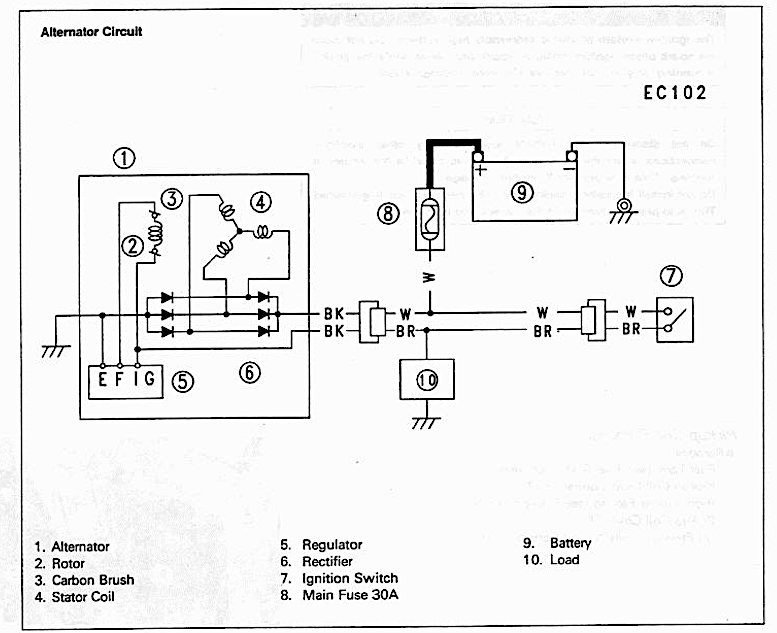
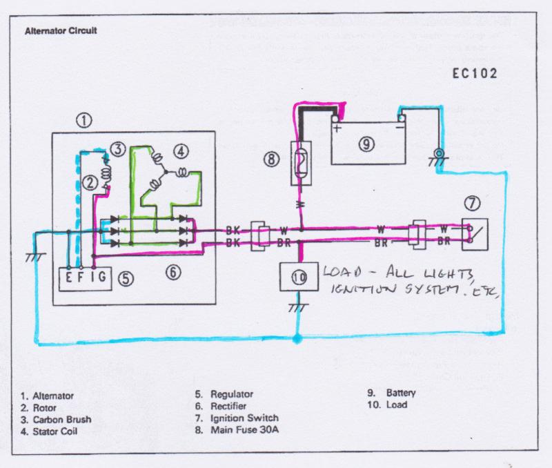
Looking at the schematic, is this how it works?

  1. Closing switch (7) provides current making EMF across rotor coil (2).
  2. Rotor (2) rotates, crossing flux lines of stator (4), creating 3 phase ACV
  3. Rectifier (6) converts ACV to DCV
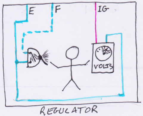
  4. Regulator (5) regulates to acceptable levels
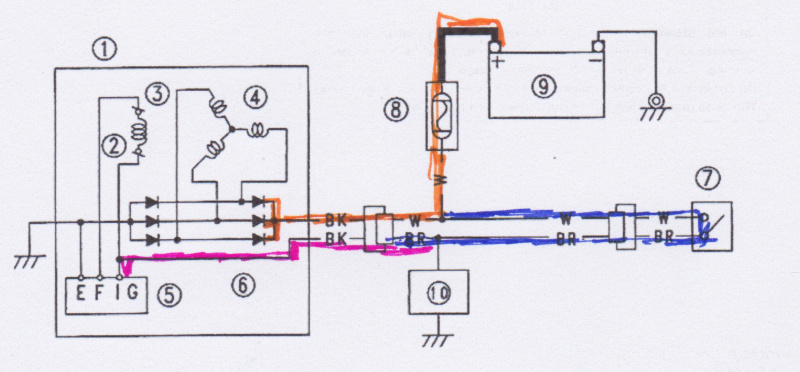
  5. The ‘BR’ wire is the load (lights, ignition, etc)and should be 13.5 – 14.x volts?
  6. The ‘W’ wire should be, essentially, battery voltage?
  7. ?? How does the alternator sense battery voltage to change field current, EMF flux magnitude across rotor coil (2)?
  8. If Alternator (1) is ungrounded, how would that cause max output voltage (per tech's statement?)
Backstory:
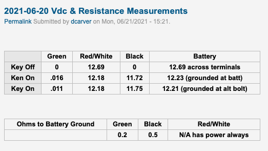
Tim's CBX sells refurbished Kawi Zx7 alternators with adapter plate. More juice, oem alt is CBX Achilles heel. Ordered, arrived, installed, vdc at battery too high, approx 17 vdc. 

Sent it back, Tim's took to their repair shop, it tested fine, but installed new regulator, just for insurance. 

Sent back, arrived, installed, > 19 vdc on my CBX. Send back to Tim's, repair shop, works great in test fixture.

Bill from Tims installed on his CBX, no problems, worked perfect.

Tech at repair shop stated alt is grounded via bolts to engine, if not properly grounded, alt would perform at max output, bypassing regulator. I use nickel based anti-seize... Could that be the problem?

https://candybuttorg.ipage.com/cba/node/1010 for entire thread, with pictures.

Thanks in Advance, Don

 
Run a temporary wire from alternator frame to battery ground. That will answer that option. Cant hardly believe anti-sieze insulates that connection. E wire on regulator should show no or very little resistance to ground. Ground wire off maybe?

 
One wire should have battery voltage all of the time. One should have battery voltage when the key is on. That wiring schematic shows the 3rd wire grounded. If the original charging system had an external regulator, make sure it is not hooked up.

 
Run a temporary wire from alternator frame to battery ground. That will answer that option. Cant hardly believe anti-sieze insulates that connection. E wire on regulator should show no or very little resistance to ground. Ground wire off maybe?
Agree. I don't think a bad ground is the issue either. This bike is pristine, all connector look factory new, and everything else works fantastic (brakes, hi/lo beam switch, horn, etc) Regarding ground wire off, OEM used wiring harness ground for alternator. Tim's CBX relies on alternator frame to bike frame grounding. The FSM for Zx7 even comments to clean the 'ears' of the alternator and the case to ensure a good ground. So maybe?

One wire should have battery voltage all of the time. One should have battery voltage when the key is on. That wiring schematic shows the 3rd wire grounded. If the original charging system had an external regulator, make sure it is not hooked up.
It's hot in the shop, over 108F but will measure when it cools off a bit.. I need an air conditioned house and shop!

 
How many wires go to that new alternator? I have A/C in the shop. Ship it here and I'll check it over the summer.  IF that diagram you posted is correct, you should be able to power up the 2 hot wires and ground the other and it should work. If it has 3 wires and the diagram is correct. Some ground the field, some energize the field circuit. Depends on internal connections. Is that a diagram for the new alternator?

 
I just had another thought. If you remove a battery cable while it is running, (don't do that) the open circuit will cause that alternator to "full field" and charge at max. This plays hell with electronics. Check for continuity from battery negative to engine. Check from frame to engine. I'm betting there is an open circuit somewhere. And it's not the mounting bolts.

 
Went to that thread. They state black wire goes to ground, red is power. Only uses 2 wires  according to his directions. Which will work if alternator field is powered internally. Somethings not adding up here.

 
I’m an electrical engineer, and that diagram makes no sense to me.  It’s got a lot of the parts you need for a generator and power supply, but not hooked up right.

 
I've replied to this in another place, I'll put a reply in here as well.

My take on its proper functioning:

The alternator body must be connected to the battery's negative terminal for the circuit to complete, this is through the bike's chassis.

The "Load" is all of the bike's electrics that need power, the ignition system, lights, plus your add-ons, heated grips, GPS, whatever.

With the ignition switch turned on, circuit looks like this:

1_paths.jpg


Everything in blue is 0V (Earth, Chassis or Ground, whichever is your preferred term). With the ignition switch on, everything in red is at battery voltage (ignoring any voltage drops in fuses, connectors or whatever). I'm calling that 12V for convenience.

The field coil inside the alternator has one side permanently connected to 12V. The regulator contains a voltage sensor that switches the other side of the field to 0V when the 12V falls below its nominal value, and switches off when the 12V rises above the nominal value.

1_regulator_2red.jpg


The little man works flat out, he is probably rattling that switch several tens of times per second, hence the intermittent, dashed, blue 0V to the Field.

As far as I know, that is how it is supposed to work.

I cannot understand how the voltage on the battery can ever reach anything above about 15 or 16 volts whatever the alternator is doing, the battery would have to be boiled dry for that to happen. The alternator can't provide infinite current, it will limit at whatever its rating says, maybe 30 amps, which the battery can absorb for quite a while before it's destroyed. And if the battery can start the bike, it's not destroyed.

However, the output voltage can be too high.

1_resistivepaths2_red.jpg


If any of the wiring/switches/connectors shown in dark blue in the above picture are resistive (dirty switch contacts, connectors ...), there will be a voltage drop between the alternator output (orange) and the fed back voltage that the regulator sees (red), so the regulator will think the voltage is low and push the alternator output up.

 
What???

You guys are speaking way above what mere mortals can understand.....

Carver, have you tried checking the fluxodynamic-capacitatingelectromagnetic-thingamabob?  First place I’d look.....

Thats all I got......

biknflyfisher 

 
What???

You guys are speaking way above what mere mortals can understand.....

Carver, have you tried checking the fluxodynamic-capacitatingelectromagnetic-thingamabob?  First place I’d look.....

Thats all I got......

biknflyfisher 
Oh, I could make it a lot more technical, that’s the simplified version. But hopefully enough to fault-find. 

 
How many wires go to that new alternator?
2, The OEM rectifier / RR (two piece) are isolated from battery ground so Honda ran a ground wire..

I have A/C in the shop. Ship it here and I'll check it over the summer.  IF that diagram you posted is correct, you should be able to power up the 2 hot wires and ground the other and it should work. If it has 3 wires and the diagram is correct. Some ground the field, some energize the field circuit. Depends on internal connections. Is that a diagram for the new alternator?
Yes, diagram is for new alternator.

Headed to shop now to measure all 3 wires, ignition on, off.. to ground.

 
What???

You guys are speaking way above what mere mortals can understand.....

Carver, have you tried checking the fluxodynamic-capacitatingelectromagnetic-thingamabob?  First place I’d look.....

Thats all I got......

biknflyfisher 
Me thinks it's easier to catch trout than fix this shit...

 
At least he is playing with the CBX with one alternator. That damn KZ has two of them and he has two KZ's.😁

 
Took some measurements yesterday...

1.png
So then, I ASSume.... All grounds are good, battery to frame, including alternator bolts. No serious voltage drops due to poor grounds. The R/W wire is providing +12V to regulator. Alt is grounding via 3 mounting bolts. Rotor field current is Black wire (11.7 vdc when battery is at 12.18 vdc)

 
Top