Itsy Bitsy Spider?

Yamaha FJR Motorcycle Forum

Help Support Yamaha FJR Motorcycle Forum:

This site may earn a commission from merchant affiliate links, including eBay, Amazon, and others.
Road map.
final+spider+electrical+dia.jpg


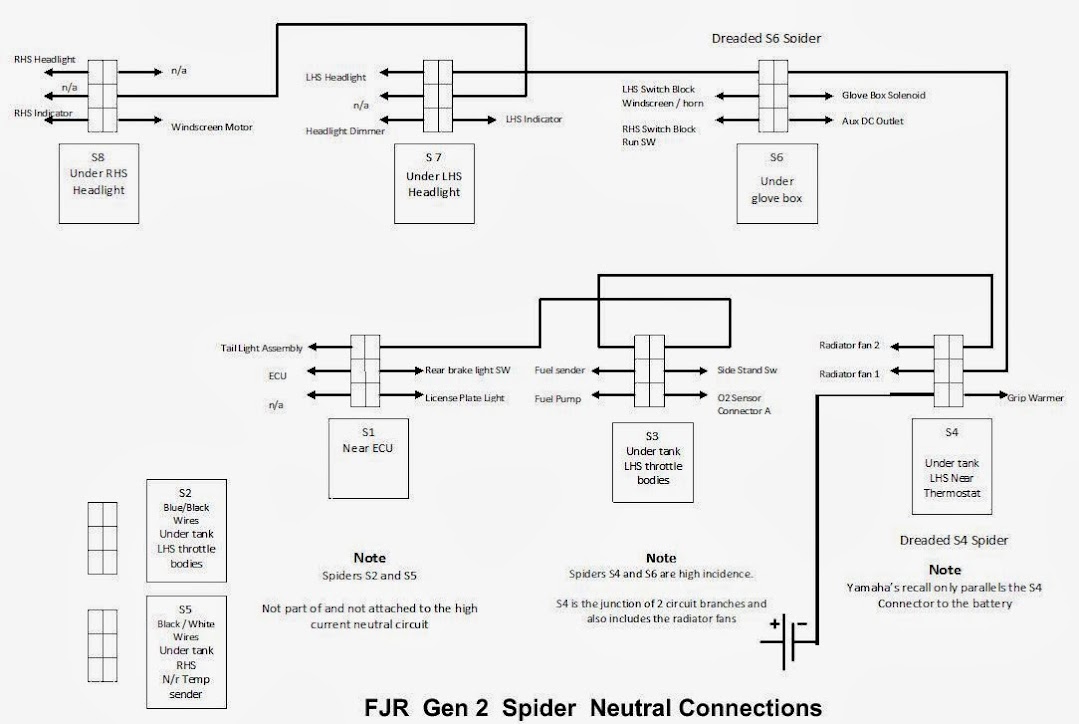
Along side the ECU S1

2 near the fuel rail connection LHS S2 S3

1 at the front under the tank, LHS near the radiator hose, the dreaded S4

1 at the front under the tank, RHS near the water temp sensor S5

1 under the LHS nose cone of the bike, below the glove box S6

1 behind the LHS headlight panel S7

1 behind the RHS headlight panel S8

The S3 and S5 have only low current sinking.

Tip 'o the hat to Queensland Ken.
Downloaded and save.. :)

 
I can't seem to find conductive grease anywhere around here. Should I use dielectric grease to prevent corrosion or clean up the contacts and use nothing. If contacts are badly burned, I am planning to cut off the connector and solder the ends together (if there is enough wire).

 
Dielectric grease is ok, but if the contact mating surface is crook, it can make things worse.

If the connector blocks look good, shouldn't be a problem, dialectic grease is an insulator.

If you do cut off and solder, solder in an additional neutral wire and run it back to the battery as well, it will help with the neutral currents.

We soldered pig tails to all the bridging pieces on my mates bike, and hooked all of them up to a 2.5 mm wire back to the battery.

4 mm may have been better, but I didn't have any. Had about 6 amps flowing through the additional neutral wire.

 
Last edited by a moderator:
Dielectric grease is ok, but if the contact mating surface is crook, it can make things worse.
I know what you mean. When I fixed one spider a couple of years ago, I removed the multi-pin connector and polished the heat-tarnished legs (not particularly corroded). I couldn't do much about the socket side but it seemed to be only slightly cooked. A couple of weeks later the issue reappeared and I ended out cutting and soldering.

 
Dielectric grease is ok, but if the contact mating surface is crook, it can make things worse.If the connector blocks look good, shouldn't be a problem, dialectic grease is an insulator.

If you do cut off and solder, solder in an additional neutral wire and run it back to the battery as well, it will help with the neutral currents.

We soldered pig tails to all the bridging pieces on my mates bike, and hooked all of them up to a 2.5 mm wire back to the battery.

4 mm may have been better, but I didn't have any. Had about 6 amps flowing through the additional neutral wire.
IMHO as long as you confirm that you have a solid connection from the battery -ve to the frame you don't need to run wires all the way back to the battery, just ground them at the nearest place on the frame. The ground connection from the battery -ve to the frame is via a very heavy wire so I personally don't see a need.

 
Sorry to hear RossKean. I had the S7 fail on my 07:

uglyspider.jpg


I thought about cleaning up the pins and reassembling the spider connection, but wasn't happy with the lack of pin tension in the sockets. So the decision was made to cut the connector off and solder the wires together. There's barely enough wire to do this job and there's no way I'd try to do it unless the nose assembly was off the bike and laying on the bench. I soldered the wires together, coated in dielectric grease, covered with shrink wrap and ty-rapped the wire to the bundle to eliminate vibration that could cause the solder joint to fail.

Good luck in your hunt....

 
It's not a real good idea to use the frame of bike for a neutral return, galvanic corrosion was the scourge of a lot of bikes.

That's why Yamaha has the neutral circuit / connectors in the first place, a good idea be it rather poorly implemented.

Have to have a look to see if there is a frame neutral, the main connector is on the motor just below the RHS header.

 
Have to have a look to see if there is a frame neutral, the main connector is on the motor just below the RHS header.
Wondering the same thing as I recalled the battery negative connecting to the engine below the right front turn signal. AFAIK there is no frame negative connection.

 
Have to have a look to see if there is a frame neutral, the main connector is on the motor just below the RHS header.
Wondering the same thing as I recalled the battery negative connecting to the engine below the right front turn signal. AFAIK there is no frame negative connection.
I agree with QK about it being preferable to not use the frame, however, it does have a good electrical connection to the motor through the mounting bolts, and so to the battery.

I am happy to use the frame as the 0V occasionally, my 0V return for the socket I use for my tyre pump uses the frame. But I wouldn't use it for long term stuff, heated anything, GPS or whatever, and not for all the bike's normal electrics. So, I would advocate running a thick earth wire round all the "spiders" rather than connecting each to the frame if you feel the need for extra routing to the battery.

Hmm. Thinking about it, my CC actuator uses the frame for its 0V return.

(Click on image for larger view)


I think I will change this ...

 
NOT a grounding spider! All the little arachnids appeared to be OK. As reported above by vabrzn , this is a separate connector. Tomorrow, I will cut the wire out of the connector and bypass it. Only the one pin seems to be cooked.


While its pretty much stripped naked, I'm going to do a valve check, change fork oil, service splines + u-joint and bleed hydraulics. Then I have to remember how it goes back together. Oh well, its supposed to rain for the next couple of days anyway.


Last edited by a moderator:
Good catch by you and vabrzn !!!

I take it the wiring loom with both the black and white connectors, access via the LHS black lower inner panel or the dash panel or the front cowling ?

I may revise the spider layout and include what you both found.

 
Last edited by a moderator:
It's pretty close to the S6. I decided to take everything apart before I even started looking. I didn't want to miss anything. Besides, I have a whole bunch of other maintenance stuff to do. Easier to accomplish on a naked bike.

Edit: Anyone know what runs through that connector? Should I assume I have it fixed once I have bypassed it? Could this cause spider-like symptoms or is there something else I have missed?

 
Last edited by a moderator:
Can you tell us what the wire colors are in that connector? There are 2-3 possible connectors with that pin count and shape.

That said, I believe that it is Coupler 3 (front cowling wire coupler). If it turns out to be Coupler 3 it goes to the lean angle sensor, gnd, meter assembly gnd, turn signals, ECU gnd and side stand switch to starter cut off relay. The gnd is joined to another ground circuit so it counts as 2 connections even though it is one wire. The solid black wire is common with the ground that roams throughout the motorcycle and is probably the burned pin.

I will mention that I have seen some wire color discrepancies between what is actually in the motorcycle and what is in the FSM.

Edit to add:

The wire colors in the coupler that I'm looking at are:

Black
Black/Blue
Green
Blue/Green
Dark Red
Black/White

Nice shop! Can I come over and work on my FJR there?

 
Last edited by a moderator:
It's pretty close to the S6. I decided to take everything apart before I even started looking. I didn't want to miss anything. Besides, I have a whole bunch of other maintenance stuff to do. Easier to accomplish on a naked bike.

Edit: Anyone know what runs through that connector? Should I assume I have it fixed once I have bypassed it? Could this cause spider-like symptoms or is there something else I have missed?
That connector is one of several that ties the main electrical harness to the front sub harness which wraps around the front of the bike under the cowling. The 6 pin connector you are holding posses the link between the S4 spider and the daisy chained S6, S7, and S8 spiders in that sub harness. Everything that connects up to those 3 spiders funnels through that connector. When it went out on you it took with it several systems up front - Headlights, indicators, Windshield motor, Horn button (neg. switched), handlebar switch block grounds, Glove box solenoid, and power receptacle in the glove box.

Yamaha's dirty little secret concerning their recall harness is that it does not address this sub harness weak link at all. Every 2nd gen. bike subject to that recall is also subject to this failure mode - and Yamaha did not do anything about it.

You have 2 choices at this point...

1. Take the whole mess and dump it in the hands of your friendly Yahama dealer and have Yamaha replace the whole wiring harness (main and sub), on their dime because the recall was not all inclusive.

or

2. Go ahead and bypass that lousy connector in a manner that will not fail again.

Your choice.

Brodie

rolleyes.gif


Kinda makes me wish I was still in the Grounding Harness business.

 
Have to have a look to see if there is a frame neutral, the main connector is on the motor just below the RHS header.
Wondering the same thing as I recalled the battery negative connecting to the engine below the right front turn signal. AFAIK there is no frame negative connection.
I agree with QK about it being preferable to not use the frame, however, it does have a good electrical connection to the motor through the mounting bolts, and so to the battery.

I am happy to use the frame as the 0V occasionally, my 0V return for the socket I use for my tyre pump uses the frame. But I wouldn't use it for long term stuff, heated anything, GPS or whatever, and not for all the bike's normal electrics. So, I would advocate running a thick earth wire round all the "spiders" rather than connecting each to the frame if you feel the need for extra routing to the battery.

Hmm. Thinking about it, my CC actuator uses the frame for its 0V return.

(Click on image for larger view)


I think I will change this ...
Just as a data point, I used the frame for grounding each soldered Spider block to the frame. The 2 ECU Spider blocks are just soldered together but not connected to the frame. I did confirm that the frame was electrically at the same potential as the Battery -ve of course.

I completed this fix at around 40,000 miles and now, over 160,000 miles later I have NOT had ANY Spider (or any other electrical) issues every since, nor expect the Spider related problems to ever reoccur. I posted pics of my fixes in one of the Spider threads if you're interested do a quick search.

 
Last edited by a moderator:
Yamaha's dirty little secret concerning their recall harness is that it does not address this sub harness weak link at all. Every 2nd gen. bike subject to that recall is also subject to this failure mode - and Yamaha did not do anything about it.

You have 2 choices at this point...

1. Take the whole mess and dump it in the hands of your friendly Yahama dealer and have Yamaha replace the whole wiring harness (main and sub), on their dime because the recall was not all inclusive.

or

2. Go ahead and bypass that lousy connector in a manner that will not fail again.

Your choice.

Brodie

rolleyes.gif


Kinda makes me wish I was still in the Grounding Harness business.
I had the S4 fix before I had any issues. A year or two later, S6 toasted so I cut it off and soldered the wired together. Now this other (non-spider) connector. If I thought there was a chance in hell that Yamaha would fix it on their dime, I'd be in favor of that - as long as it was done by someone who had some level of competence. I have never heard of Yamaha even acknowledging that a problem beyond S4 even exists, much less covering any repair costs.

Anyway, for this one, I cut the wire on either side of the connector and spliced them together. Hope that's the end of it.

 
Brodie, where can one buy the connectors you used? As you suggested I want to bypass those lousy connectors.

 
Ross pointed me in the direction of this thread and it seems the previous owner of my 07 already did the connector bypass that a couple of y'all mentioned in here. But last weekend I had windscreen, horn and glovebox failure.... I'm not sure about the charging port in glove box since I can't access it everything else on the bike works perfectly fine. I took the tank and left side fairing off, got to all the spiders they all look fine, removed the spiders and cleaned them up, fiddled around and actually got power back to the 3 things. Went to put the left fairing back on and tested everything afterwards and no power to those 3 same things again. I've checked every connector I could find by the left fairing again to see if something got knocked lose with no luck. I found the wire the previous owner jumped was showing some fraying so I removed his connector and added a new one (the purpleish one) but still no luck. I've put about 3000 miles on the bike since I got it last year... Yeah I don't get to ride much with my job these days, but this is the first time I've had any electrical issues with it. Yamaha shows the s4 recall was done. Any advice?


Top