A couple of years back I opened up both connectors and found the dreaded corrosion there too. Cleaned it and silicone greased the connector up. Fast forward a couple of years to now . My '05 had started to surge a little excessively at idle recently, and remembering this post I dug it out to go over these connectors again and I'm a bit confused. I mean, I could definitely see how a corroded connector could be rersponsible for the engine not running right, but I can't see how these connectors would do it.
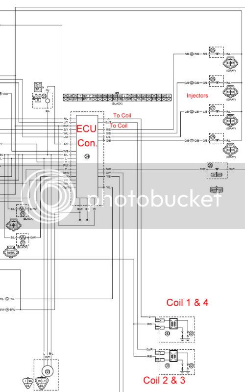
I went through all of the pins in these two connectors and traced them out to see if I could find something that makes sense. BTW, the below is specific to the 04/05 wiring harnesses. The '03 wiring and connectors appear to be similar, but a little different
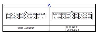
The "A" connector has 11 pins:
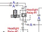
Red/Yellow - Headlight Relay #1
Brown/White - Turn Signal Relay output
Green/Black - To Headlight Relay #2
Light green - to Neutral Indicator Light
Brown/Green - Turn Signal Relay input
Red/White - Instrument Panel power
Black2 - Instrument Panel ground
Yellow/Black - ECU trigger to Headlight Relay #2
Green/Yellow - ECU trigger to Radiator Fan Relay
Brown/Black - Power to Radiator Fan Relay
Blue - Power from Radiator fan relay to fan motor
The "B" connector has 10 pins
Sky blue/White - Control signal (neutral) to Accessory Box Relay
Brown - Power to Instrument Panel back-lights and Accessory box relay
Green/White - Fuel level sensor signal to INstrument Panel
Blue/Red - Power to front running lights
Dg - Power to right front turn signal and indicator
Chocolate - Power to left front turn signal and indicator
Black - Ground for front running lights, front turn signals and windshield drive
Sky blue - Down signal to windshield drive
Brown/Yellow - Power to windshield drive
Light green - Up signal to windshield drive
The Brown and Black wire shown in two different posts as having the most verdigris corrosion buildup goes to the radiator fan relay. :huh: That surely would not cause these kind of symptoms. I'm not saying cleaning these connectors didn't resolve some folks idle surging problems, but I sure the heck can't see why it would. :blink:
Maybe just moving the entire harness around is wiggling something else up in the nose, that actually does have something to do with the engine management?