Lost Power

Yamaha FJR Motorcycle Forum

Help Support Yamaha FJR Motorcycle Forum:

This site may earn a commission from merchant affiliate links, including eBay, Amazon, and others.
+1 on the holy crap. Nice that you found it before it stranded you, Don.

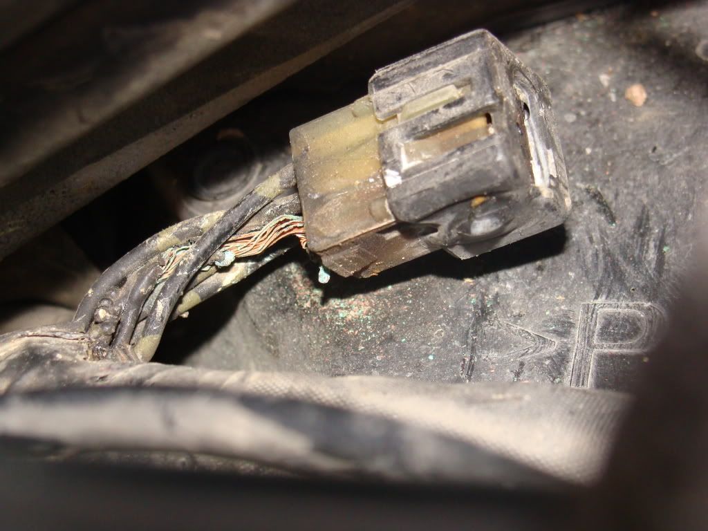
In all of my years of electrical and electronic service work, I have never seen a design like that one. They took a regular multi pin female spade connector and fashioned a 6 pin male spade shorting plug to fit into it. Begs the question, what current are each of those circuits carrying, because they all eventually end up going through the one single connection that goes to the single ground wire. I'm betting that, like the single contact in the ignition switch, that slip fit connection is being overtaxed beyond its rated current handling capacity.

I'm also thinking that all 2nd genners should do this connector survey, or possibly suffer the consequences...

 
Well this is quite the revalation.

2 weeks ago while on my was from KY to Ct on the interstate the engine cut out twice when I used the left signal to pass. Been fine ever since.

I gotta get under that tank ASAP. Thanks for the info. I think you just saved me from an eventual tow.

06 model with 45K on it.

 
This is a classic problem with most electrical when things are done as Yamaha has done with their wiring harness.

I see a whole lot of problems that need attention by Yamaha. To many conection points with space between the wire and the connector,=heat build up. wire is ro small.to many.

The ground wire needs to connect in series from point to point and return to one central grounding point, If any soldiering is done on any wires or connections it should be silver soldered much higher temp rating. It seems that most of the farkles that are being put on as well as the oem electrical is electronic, and the harmonics playing a role in the heat issue as well as all the other things that were found. And lets not forget about heat from the bike itself it runs at some pretty high temps.

The idea that was proposed of using that terminal block and running the grounds back through it is an excellent idea. Maybe we will see something like this on the next gen bikes when they make changes

If Yamaha were to really look at this and fix the electrical problem the cost would increase some and we would get a new wiring harness with bigger wire and better way to connect wires, with a grounding system wire sized at least two sizes larger than calculated just to handel the harmonics and the engine heat build up

Just some food for thought. I have an 05 and no problems yet being stranded yet, Only one incident at wfo in Colorado in the mountains, stopped to take a pic and the bike would not fire, waited a few minutes and fired have not had another incident......

Interesting post and a lot of creativity out there in problem solving these problems for Yamaha and than they raise the cost of the bike and we pay and pay.................

 
I'm also thinking that all 2nd genners should consider shopping for clean, low-mileage Gen 1s..........
Fred, FIFY. :assassin:

Oh my gawd no! And roast their precious nutz? Think of the childrenz!!

[SIZE=8pt]much better to stick with these 2nd gens with all their electrical nightmares... [/SIZE] ;)

 
Last edited by a moderator:
"calculated just to handel the harmonics"
Huh? :huh:

We've got 3 phase AC power with reactive loads in our FJR ground wires? :unsure:

Naw! We got corrosion is what we have. I found corrosion in many electrical connectors when the bike was only a year old. Just a tiny bit but the beginings of bigger things to come. I disassembled and treated all the ones I could get to. I didn't do this one though. Thinking about it now, (hind sight is always so clear) I do have a couple of other "glitchy things going on, but so suttle you would never recognize them up front. My Datel, which I tied into the running light is reading about .2 lower than it used to, and I get a tick in the radio when putting the turn signals on.

I'm getting into it today. I'll report back what I find.

 
Several thoughts on corrosion. The pix below clearly shows a corroded wire. The splooge below the connector, on the black plastic, was because I scrapped the wire with a flat bladed screw driver. I was having difficulty seeing into the cavity, couldn't tell if the wire still had insulation or not.

I live in dry country, minimum salt air exposure. The CrZy8 rarely gets bathed, so little opportunity for water intrusion from that avenue.

I wonder if the corrosion happened inside the connector first due to dissimilar metals or after the insulation fried, or a combination of both?

Electrical guru's, how much current would it take to melt a wire of this gage? What circuits are grounded by this loop? What circuit(s) could draw sufficient amps to cause heat damage? All my electrical accessories are grounded to grounding blocks going to B- (old skool terminology kiddies, got filaments?) or directly back to B- and run through relays.

My guess is as stated above, the system is marginal, any corrosion or excessive draw for whatever reason leads to problems.

Burnt.jpg


Look closely, you can see heat damage to the connector. Wouldn't this indicate the problem started at the connector?

I want to cut the connector off and see if the bike still runs OK.. I think everything has welded below the connector, which is why it's been running good since last August when I first posted about Weird Electrical Stuff.

Addi tonally, what good does it really do to install a new harness if it's similarly built? Unless there was a bad lot run, it seems like this would just happen again.

How can we chase down part numbers to see if they have changed?

 
I got in there to take a look and I found exactly what was said. I had a very mild case of it, but trouble was coming no doubt. I had one connector in the corner that had produced enough heat to discolor the plastic connector. It did not damage the wires or their insulation. So I removed the spider, got in there with some jewlers files and picks and contact cleaner to do the best I could. I then coated the pins with contact enhancer, sprayed corrosion preventer in there, and filled the little plastic cap with silicone grease and reassembled it. I also gave the same treatment to the other 2 similar connectors I could find. One on the opposite side of the radiator and one on the left side of the engine.

Now this is interesting. I have a Datel VM that I wired into the running lights 2 years ago. Because I tied into a loaded circuit it reads .3V below what the battery actually is. Fine, it still is a valid refference point. But lately the Datel has been reading .5 below. I assumed I had some increased resistance in the Datel wiring. Now that this connector has been cleaned, the Datel is reading only .1 low. This tells me I have had this resistance for a very long time.

I would suggest everyone get in there and clean and protect this connection. Remember, if the engine shutting off doesn't frustrate you, the potential wiring harness fire sure will. Not that there are any reports of this....I'm just saying.

 
The corrosion potential needs to be addressed first via cleaning and coating the contact assembly - wire ends and shorting pins - with some dielectric grease. But it's the current load on that plug that really is the question.

The '08 SM is confusing when it comes to tracing what circuits feed the left front point connector plug in the picture. The circuit diagram lacks a clear picture of these common ground "point connectors" and what color code wires feed them. The various plugs are shown however in the cable routing diagrams. There are several components that go to ground in the front of the bike, but none have the Black with Green spot wires that actually connect to the plug in question, at least from what I can tell from my diagram. My '08 SM infers a common ground connection that may apply for at least the following:

1. (98) Windshield drive unit

2. (96) Headlight

3. (92/93) L/R turn signals/position lights

4. (74) Windshield position switch - common with (76)

5. (76) Horn switch

That's a lot of potential current draw if that's indeed the case, and all or several are activated.

I suppose the thing to do is extract the six-pin shorting block from the left front plug, turn on the key, confirm what components are dead due to an open ground, then reactivate them one at a time with a single ground to each pin in the block. If I get time before I fly back out to the woods I'll do what I can. I can also measure the amperage per ground wire. Or someone else can if they get the time. We really need to confirm what's components are connected to that plug and reevaluate the setup.

Gary in Fairbanks.

 
Last edited by a moderator:
My '08 SM infers a common ground connection that may apply for at least the following:
1. (98) Windshield drive unit

2. (96) Headlight

3. (92/93) L/R turn signals/position lights

4. (74) Windshield position switch - common with (76)

5. (76) Horn switch
I was just thinking that given the above list of electrics presumed to be grounding through this ground block is there any correlation between really fried ground blocks and one or more of the following farkles:

1. higher wattage bulbs

2. after market horns that are not running on a separate, after market wiring harness

3. heated gear or any other high power electric gadgets

4. ignition switch failures (could some of the ignition switch failures been caused by this ground block problem or vise versa?)

Also would be interesting to find out if any of the affected bikes show any significant ohms b/w the frame, engine and B- as something like that could in theory mean that say the frame (with all the -ve connections) was grounding (may temporarily, like during some maintenance work etc.) though this comparatively low current ground block.

 
Last edited by a moderator:
Several thoughts on corrosion. The pix below clearly shows a corroded wire.
Geezus Don! That is a frickin' mess! Sorry to see :eek:hno-smiley:

I wonder??

Maybe the "initial" ignition switch failures, might have been the first indication of a weak ground/wiring harness in the Gen II's?

Also, Yamaha DID put a larger alternator in the Gen II's.

 
Last edited by a moderator:
IIRC the relay unit that handles things like the headlights is one of the grounds there, but the Fuel pump is also run through this junction. I think I remember seeing it through the relay unit, so I'm thinking the headlights and fuel pump is quite a bit of current there.

Mine didn't exibit problems until 75,000 miles (2006 model) and I have stock headlights and horn. I do have lots of electrical farkles, but they all run directly off the battery via relay.

 
Don

That's quite a picture, I'm going to pull my tank this week to check out my ground shunts. Two years ago I too applied dielectric grease on all the electrical connectors I could reach. I don't remember disassembling these shunts and greasing them. I hope I did, it would make an interesting study. I think the root cause is corrosion. Once the corrosion starts it causes resistance - just like the small contact in the ignition switch. We are looking at a classic electrical thermal runaway. Resistance begets heat which begets more resistance which begets more heat... until a meltdown occurs.

Burnt.jpg


I think the wire with the insulation melted off is the lead from the shunt to ground. It is carrying the load from the other 5 wires.

I don't think the ignition switch had any direct affect on this ground shunt. There are no
ground
wires leading to the switch, I had to provide my own for the relay.
At this point, my fix would be to disassemble every ground shunt and grease them up. If there is any evidence of heat damage some surgery is in order. If they are kept clean and "dry" they should work as designed. Keep in mind, this is the main harness that's involved - the central nervious system. I don't see any add on or slick gismo to apply here.

This is why I work real hard to keep any extra added electrical loads off the bike's circuitry. IMHO, a sub panel or fused lead straight from the battery and grounds returned to the battery is the only way to go for farkeling the bike.

If anybody has a good method of removing the corrosion and returning the crimped connector pins to pristene condition, that information sure would be appreciated. I think the best way starts by extracting the pins from the plastic and go from there.

Brodie

 
Last edited by a moderator:
I have one silly question...

So far the count is 3 of these shunts on the bike. Are we positive that all three are ground connections? Has anyone probed them with a meter?

:dntknw:

Brodie

 
I have one silly question...
So far the count is 3 of these shunts on the bike. Are we positive that all three are ground connections? Has anyone probed them with a meter?

:dntknw:

Brodie
I just did the one under the seat above the ECU plug yesterday, but didn't take notes. There was one pin at just above 0 ohms to ground, the rest were at some resistance above that (component resistance?), plus B+ anywhere from 12-0.2VDC when powered up as expected if they share a common path to ground. The wiring diagrams show these poorly, if at all, and my '08 SM fails to even show the color codes of the Black/Green spot wiring common to all plugs. The assumption is that they are the point connectors shown in the wire routing drawings in the front of the SM.

If the single ground wire were compromised, then some high resistance and resulting weird voltage could occur in component wiring, potentially giving rise to the trouble codes some have seen.

I proposed what you asked - probe them with a ground source to see what component returns to life after the shorting connector is removed, and also measure the potentially cumulative amperage draw through the ground. I won't have time for that for several days unless I'm stuck here in town longer than planned.

Either way, clean connections are something to work towards, as may be a bigger gauge of ground wire for the troublesome forward plug. The wire size for the ground seems small for the potential demands. That a single similarly sized wire can handle the current of 4-5 others in a common connection seems somewhat odd to me.

Gary in Fairbanks

 
Last edited by a moderator:
I have one silly question...
Brodie
Well since it's not Friday, I will ask another silly question.

I have just ordered a tube of DC 4 ELEC/INSULATING COMPOUND that people here have been recommending.

I am somewhat hesitant putting grease of any kind on electrical connections, however. I mean what happens when that area warms up softening up the DC4 which then could run into the connector and b/w the pins.

Do compounds like DC4 actually increase electrical conductivity or decrease it if the compound finds it's way b/w the two electrical terminals which are supposed to be making contact?

 
Do compounds like DC4 actually increase electrical conductivity or decrease it if the compound finds it's way b/w the two electrical terminals which are supposed to be making contact?
That doesn't happen. Electrical contacts work by making metal-to-metal contact by concentrating the mating force into a small area. Dielectric grease is an insulator. Its function is to coat the metal surfaces of the contacts to prevent water and corrosive stuff from attacking them.
olsonm3915, thanks for the response. Am i correct in my understanding though, that if by chance this compound does get on the parts that are supposed to make metal to metal contact it will in fact reduce the conductivity, thus increasing the resistance? Like for example you've put the DC4 on the connector then unplug it to check or for whatever other reason, then when re-assembling you plug it back in there is a chance that DC4 will partly end up b/w the connector surfaces making things worse - this is what i am concerned about. Is this logic correct?

 
Top