Donal
Well-known member
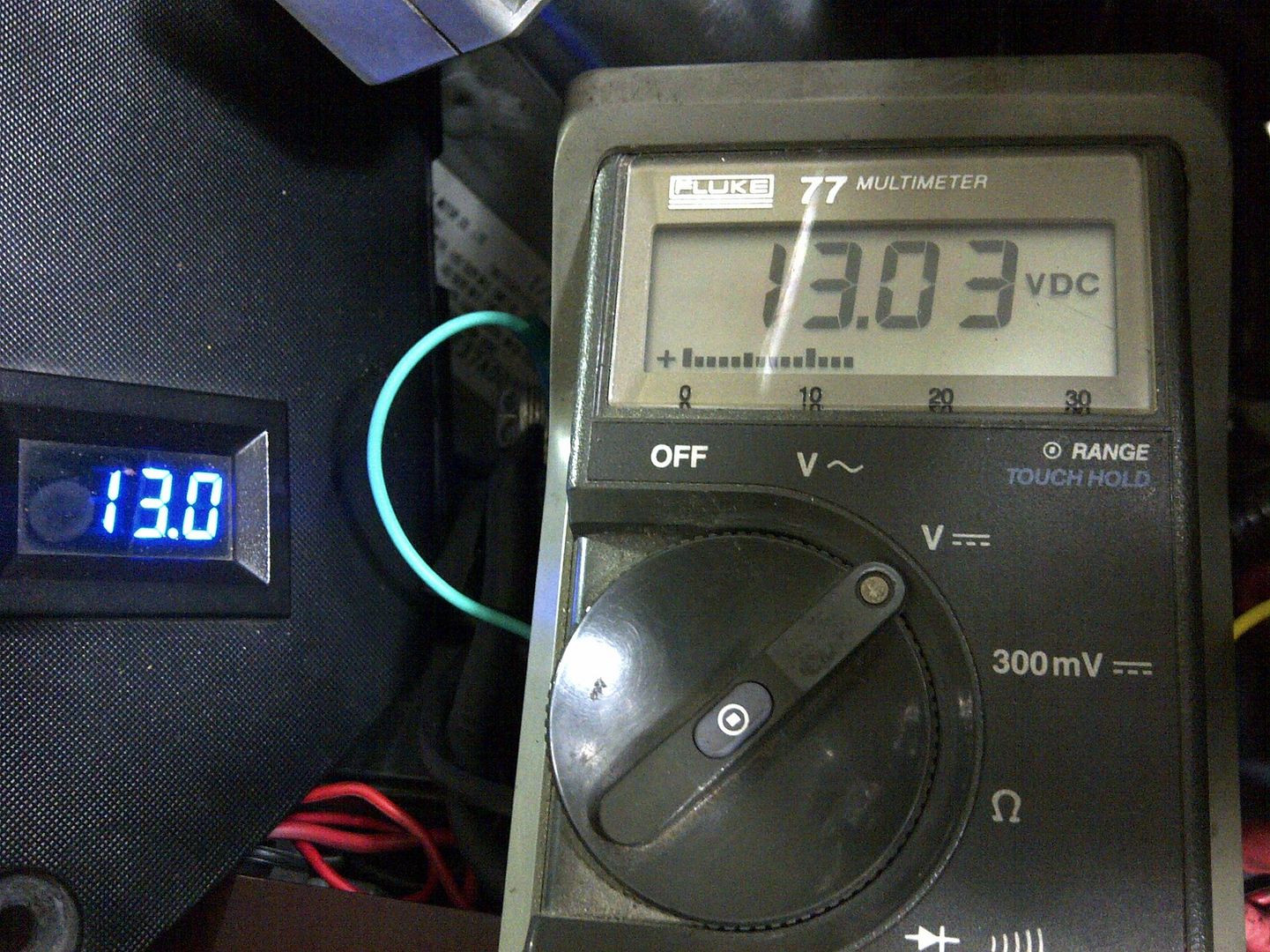
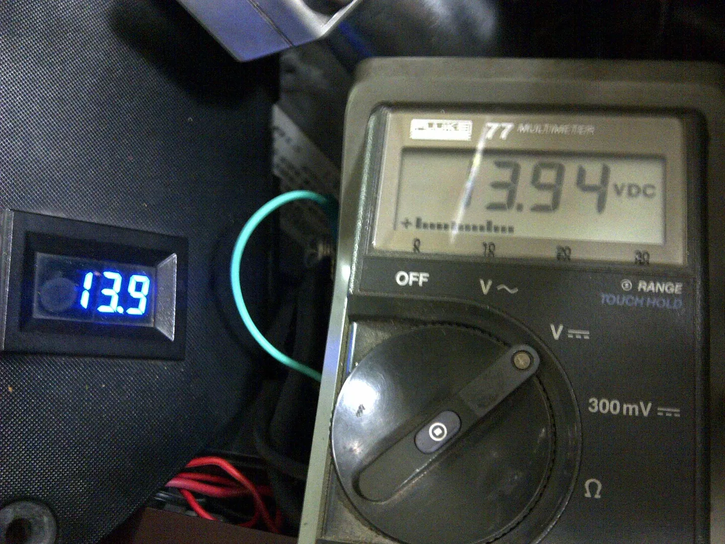
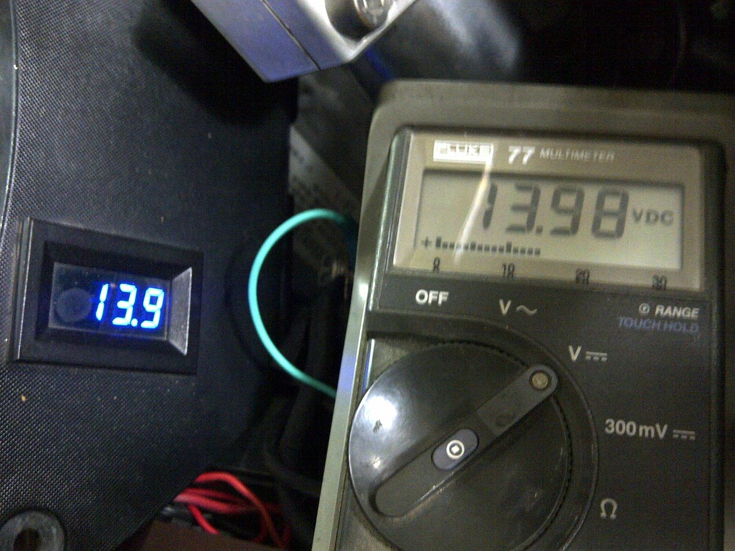
Not really sure what you mean by "it's leaking any current". The ABS system could draw additional current (if the pump is running) and thus cause additional volts drop, but it won't cause any current to go astray. IMHOExcellent point Fred, 'crisply' made (pun intended!)
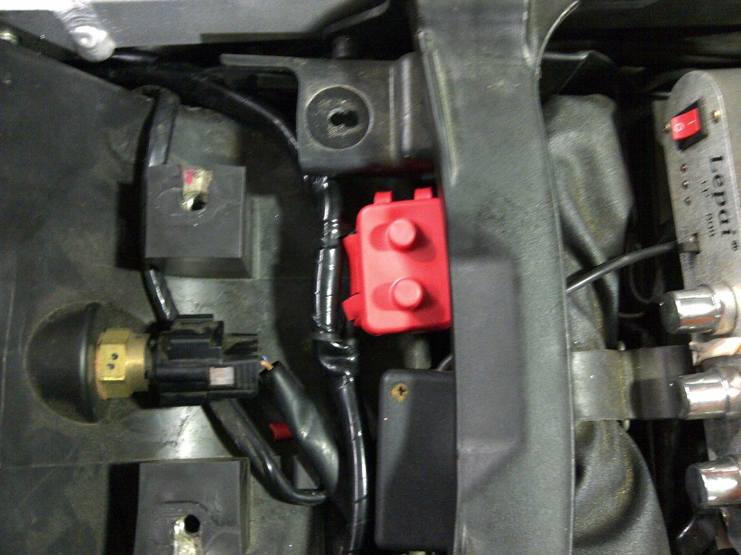
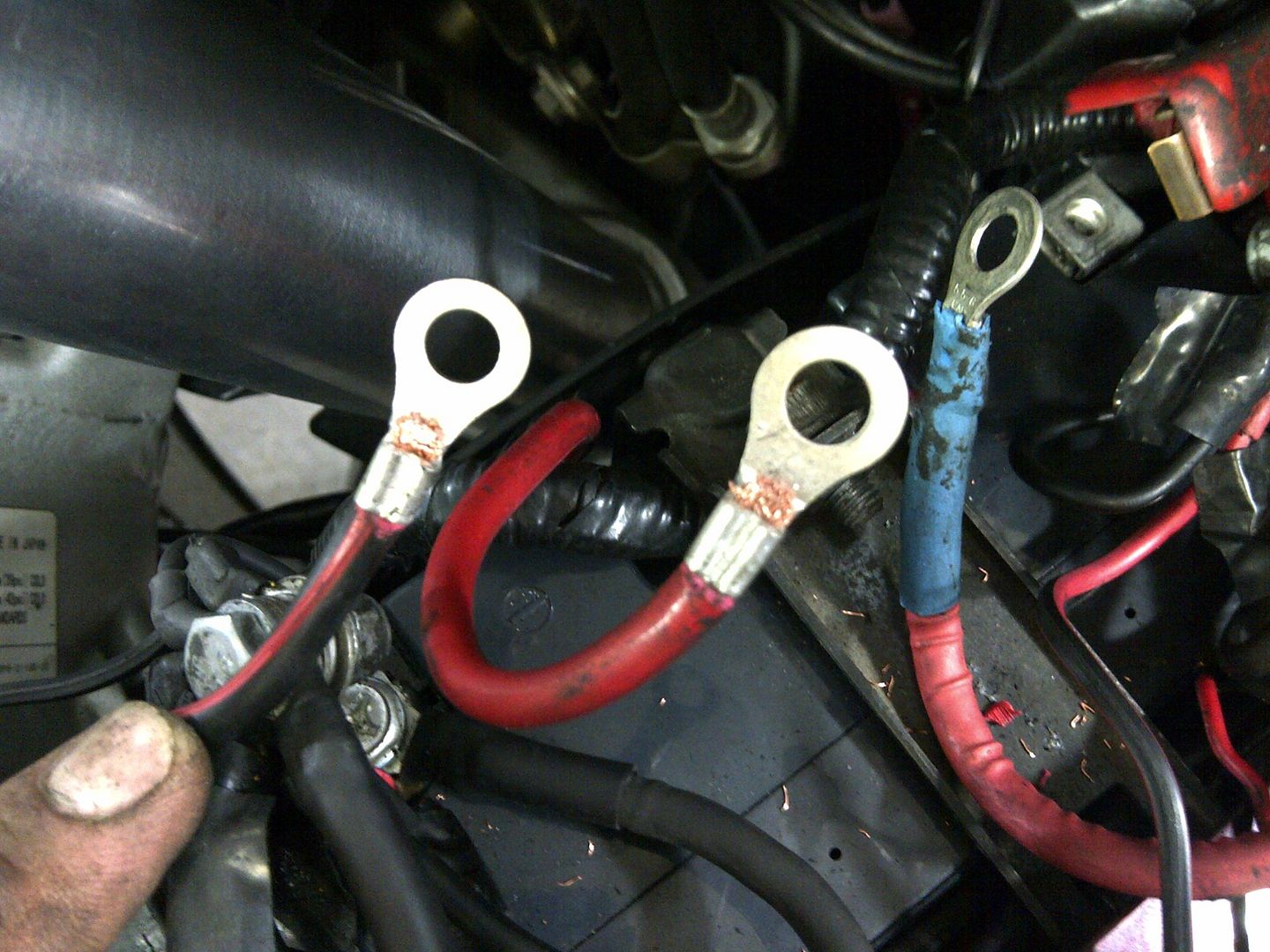
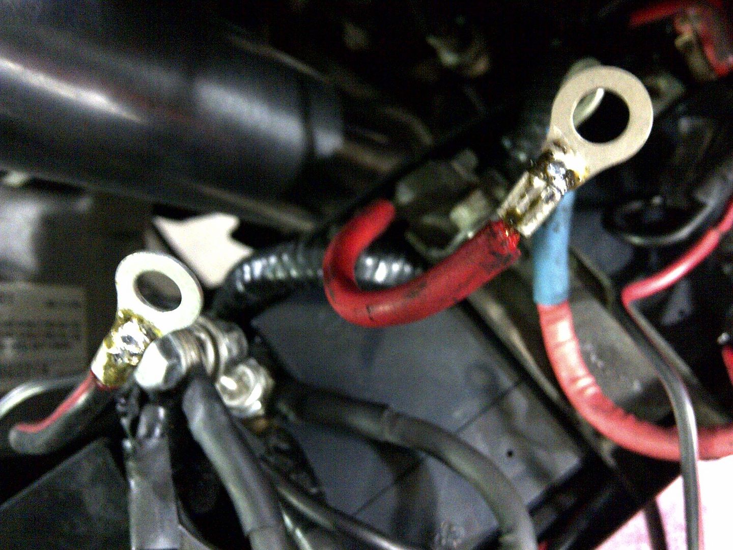
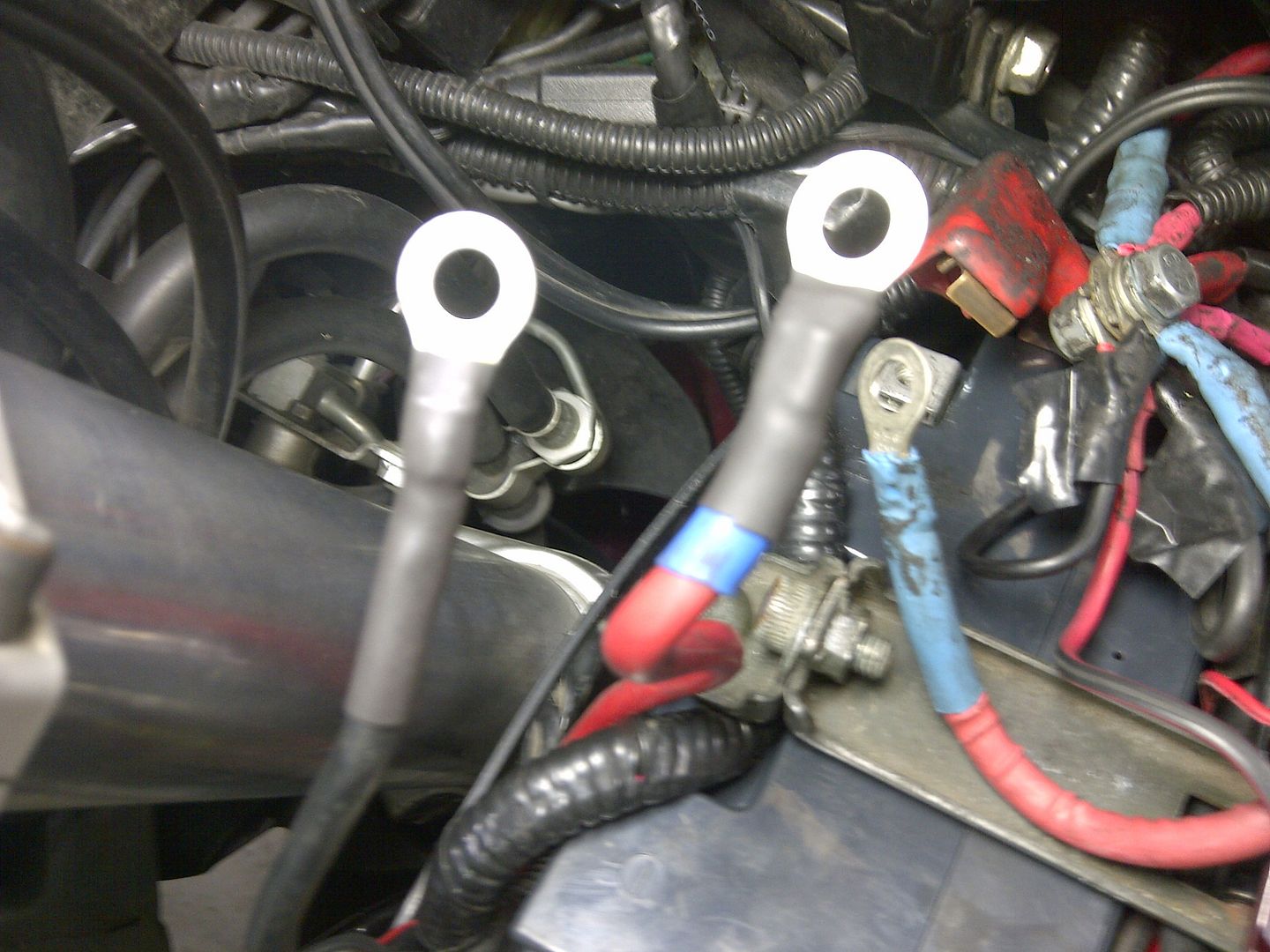
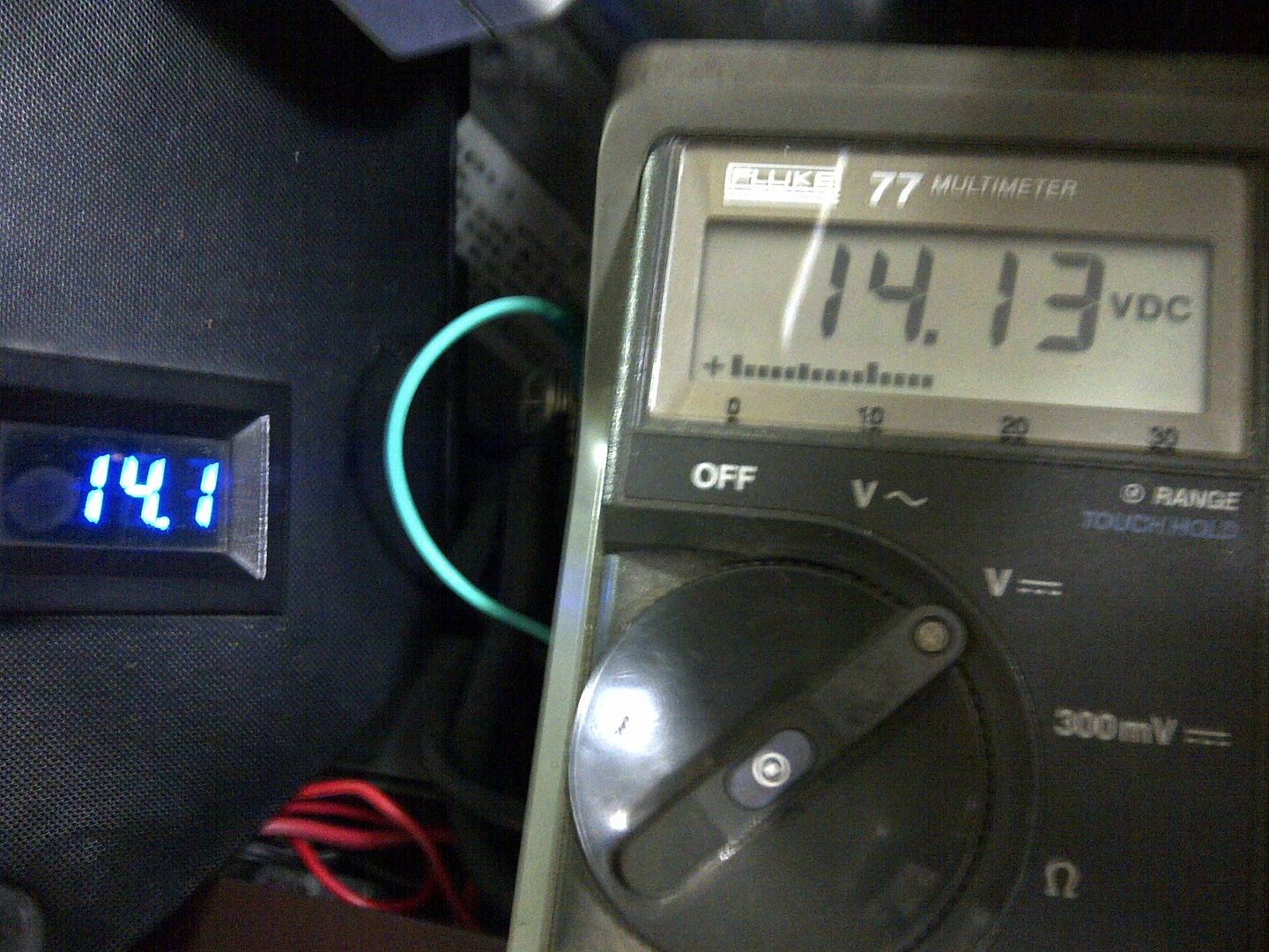
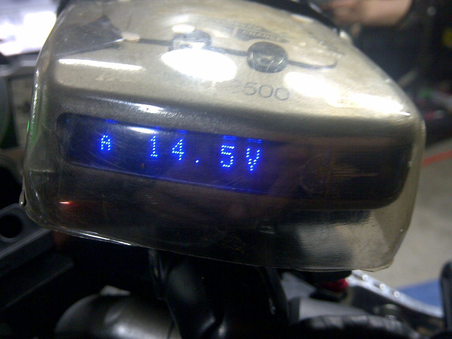
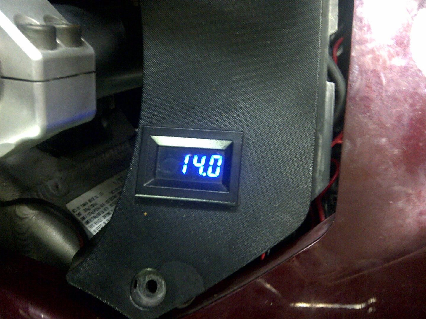
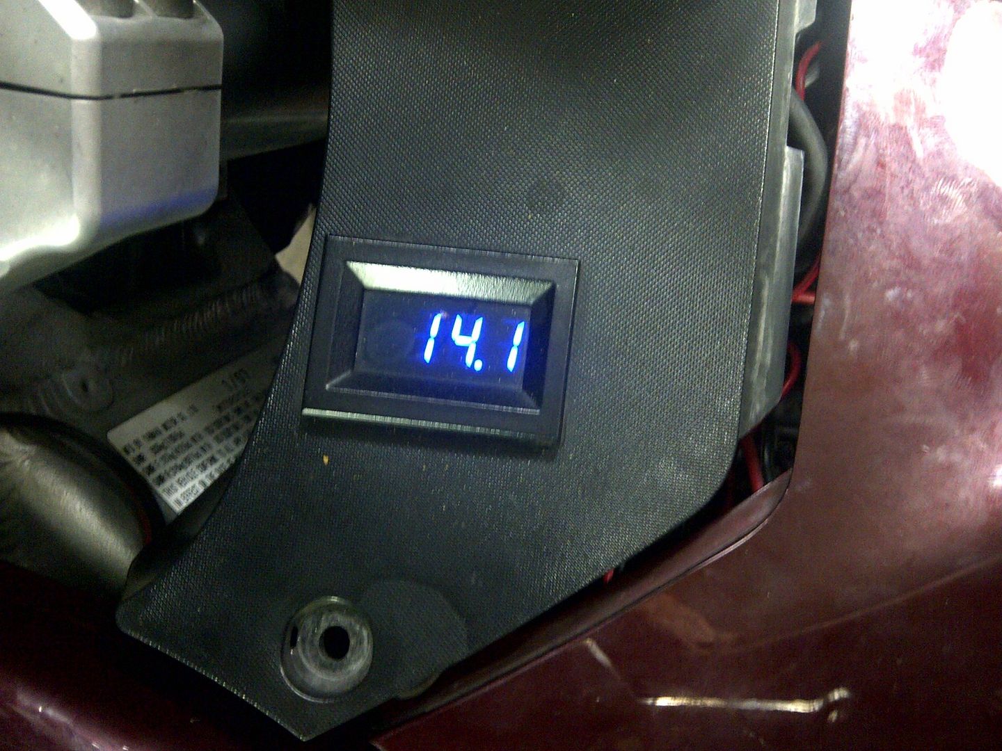
On that same note, I *finally* located the power wires for the ABS brakes. They are buried toward the inner side, center, of the bike's width, above the RR plate. The connector looks like a beotch to get at - it's connected to the bracket housing the pump, requiring disassembly at arms reach while laying on the floor. I so want a lift. This connector is the last of the power circuit I've not had apart. I doubt it's leaking any current, but it would be 'curious' to disconnect it and see what happens to the VDC drop from batt + to RR output +. Thoughts? Worthwhile to chase it down since I'm this deep into it or just not worth the ROI?
One other connector I've not been into for inspection is the ECU - same question, leave alone or should it too be looked at, just for grins and giggles?
If you want to discover if it is drawing any additional current go with Ionbeam's advice.
Just my two pence worth

Don
Not really sure what you mean by "it's leaking any current". The ABS system could draw additional current (if the pump is running) and thus cause additional volts drop, but it won't cause any current to go astray. IMHOExcellent point Fred, 'crisply' made (pun intended!)
On that same note, I *finally* located the power wires for the ABS brakes. They are buried toward the inner side, center, of the bike's width, above the RR plate. The connector looks like a beotch to get at - it's connected to the bracket housing the pump, requiring disassembly at arms reach while laying on the floor. I so want a lift. This connector is the last of the power circuit I've not had apart. I doubt it's leaking any current, but it would be 'curious' to disconnect it and see what happens to the VDC drop from batt + to RR output +. Thoughts? Worthwhile to chase it down since I'm this deep into it or just not worth the ROI?
One other connector I've not been into for inspection is the ECU - same question, leave alone or should it too be looked at, just for grins and giggles?
If you want to discover if it is drawing any additional current go with Ionbeam's advice.
Just my two pence worth
Don