


UselessPickles
Making Grand Canyon replicas from air boxes...
Just thought I'd share a few details about how my installation turned out. I used FJRCarShopGuy's walkthrough as my primary guide, but wanted to install the servo under the gas tank the way Smitty does for AE models.
Here's some questions I had before beginning (with answers in the first post you you don't have to do a lot of reading): https://www.fjrforum.com/forum//index.php?showtopic=113115. Most important is the new dip switch settings as compared to FJRCarShopGuy's post.
The physical connection of the servo cable to the throttle pulley is covered many times on the forum, so I won't go into much detail on that. I basically used a small button-head bolt from a hardware shop through a hole drilled in the little tab on the throttle pulley. A standard nut tightens the bolt to the tab, then a nylon lock nut at the end of the bolt holds the servo cable connection on the bolt.
I stressed quite a bit about the drilling and throttle connection, but it ended up being the wiring that was the biggest pain for me (figuring out how to route wires, when to group them together, when they should split up and go their separate ways, how short to cut the wires, etc.). Here's what I ended up with...
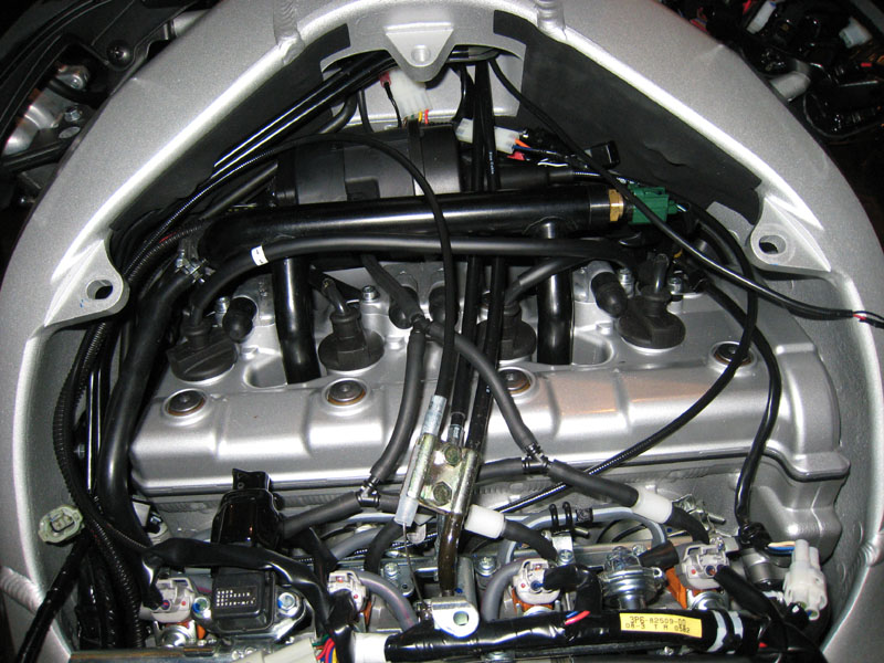
Somehow my wiring doesn't look nearly as tidy as Smitty's pictures, but I still may have some room for improvement by just tucking things away better. Here's the overall view:
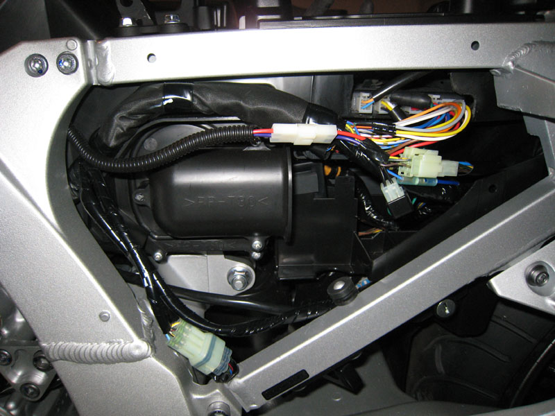
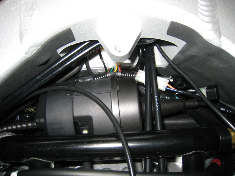
The servo tucks nicely behind the water coolant pipe. It is a bit of a pain because you need to drain about a quart of coolant and remove the pipe to get the servo in there, but it's a nice hiding spot for it that doesn't use up any precious under-seat space.
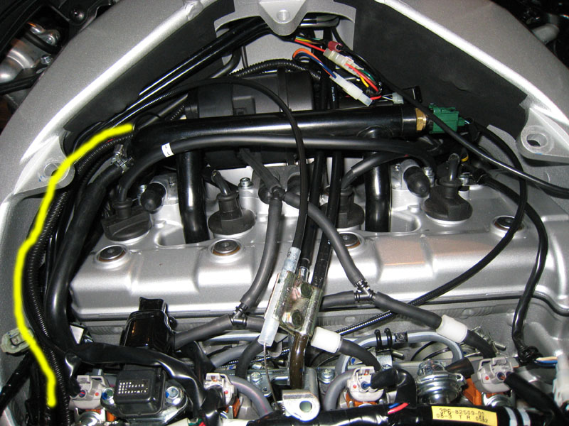
I used 1/4" wire conduit that I bought from a NAPA shop, which wastes much less space than the large conduit that comes with the Audiovox. The yellow line shows you the wiring from the servo back to the brake wires. To the right of the servo is the connector for the control panel and a couple extra connectors that I added (more details later).
You can also see the vacuum lines there. I hooked into all 4 cylinders with a 3/16" mini check valve on each line before bringing them together with a couple 3/16" Y connectors. I don't have a vacuum reserve canister right now. I'll see how it works without one and can easily add one later if needed.
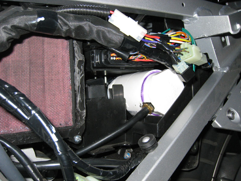
And now for some more details on that mess of connectors:
The wires from the control panel are not shortened. I tapped the (grey?) backlight power wire for the control panel directly into the red switched power wire way up near the control panel so that the backlight is always on when the ignition is on, and so there's only 5 wires to try to wrap up and hide along the handlebar.
The red power wire from (2) goes only a short distance to (3). The power and tach wires from (4) run a short distance down to the giant brain stem of stock wiring and up into the fuse/battery area where I made my power and tach signal connections almost exactly like FJRCarShopGuy did.
All wires from (2) and (3) go directly back to the the main harness on the servo (except for the red power wire, which goes from 2 to 3). All of this was cut to length (about 5 feet of excess removed!).
The ground wire from the control panel goes through the bullet connector (5) back to the servo and taps into the the ground wire coming out of the servo's main harness, very close to the servo (wiring experts: is this a wiring sin? should I be watching for grounding problems?). The ground wire from the servo follows the large coolant hose that's connected to the coolant pipe. It goes under the frame then back up on the other side where it's mounted to an existing bolt:
The purple and red brake wires from the servo's main harness follow the frame on the left side of the bike (in a separate conduit; visible in the first picture) to the main ECU harness area where I tapped into the stock brake wiring. I added a connector right near where I tapped into the wiring:
I like having connectors everywhere so that things can be disconnected and moved out of the way as necessary for other farkling and maintenance. The connectors came from RadioShack. I crimped AND soldered the connectors to the wires for a reliable connection.
Unfortunately, it's freezing cold and snowy here, so I can't go for a test ride to verify that everything works. My bike is still stripped down for now, so I can take more pictures of other details at your request. Feel free to ask for details that I left out or to tell me if I did something horribly wrong so that I can fix it")
~Jeff
-------------- UPDATE --------------
I have since shortened the wiring more for a much cleaner appearance and to keep the wiring away from the coolant pipe:
-------------- ANOTHER UPDATE --------------
I finally added a vacuum reserve canister because the accelerate button for the cruise control was quite ineffective. The cruise control seems to engage a bit quicker now and the accelerate button actually works! I made my canister out of a 2" PVC coupler, two 2" PVC plugs and a 3/16" threaded brass nipple thing. I found a nice place for it that only required a very slight dremeling in one of the ribs on the top side of the rear fender where the canister sits (right next to the lock barrel that actuates the seat release mechanism) to allow it to fit under the tool tray:
I used some basic PVC primer and glue to glue the PVC parts together. I only inserted the plugs about half-way into the coupler to make it as long as could fit in the space under the tray. That nasty looking black junk is some silicone gasket maker I had left-over from installing my Remus hexacones, and it seems to do a good job at sealing the threads of the brass nipple. The canister was still holding vacuum when I checked today after a full 2 days of no riding.
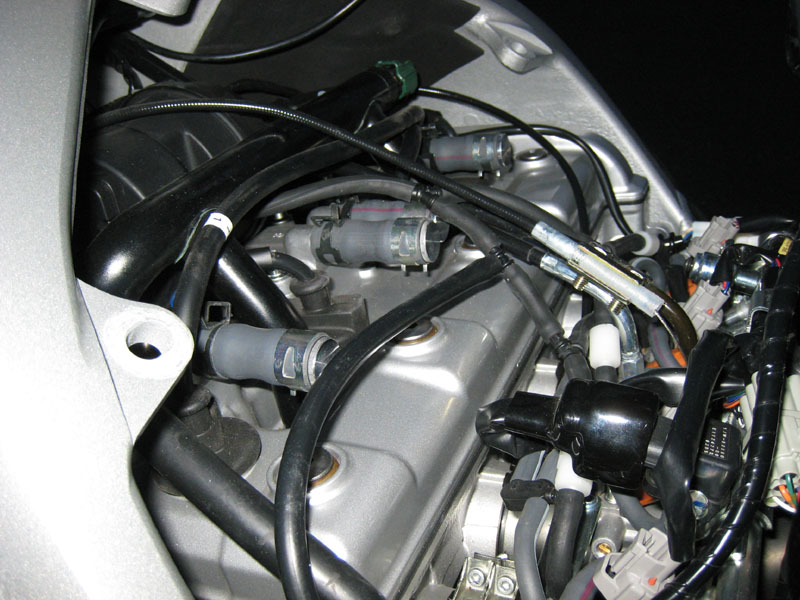
And here's the hose from the canister where it meets up with the rest of the cruise control's vacuum hoses:
Here's some questions I had before beginning (with answers in the first post you you don't have to do a lot of reading): https://www.fjrforum.com/forum//index.php?showtopic=113115. Most important is the new dip switch settings as compared to FJRCarShopGuy's post.
The physical connection of the servo cable to the throttle pulley is covered many times on the forum, so I won't go into much detail on that. I basically used a small button-head bolt from a hardware shop through a hole drilled in the little tab on the throttle pulley. A standard nut tightens the bolt to the tab, then a nylon lock nut at the end of the bolt holds the servo cable connection on the bolt.
I stressed quite a bit about the drilling and throttle connection, but it ended up being the wiring that was the biggest pain for me (figuring out how to route wires, when to group them together, when they should split up and go their separate ways, how short to cut the wires, etc.). Here's what I ended up with...
Somehow my wiring doesn't look nearly as tidy as Smitty's pictures, but I still may have some room for improvement by just tucking things away better. Here's the overall view:
The servo tucks nicely behind the water coolant pipe. It is a bit of a pain because you need to drain about a quart of coolant and remove the pipe to get the servo in there, but it's a nice hiding spot for it that doesn't use up any precious under-seat space.
I used 1/4" wire conduit that I bought from a NAPA shop, which wastes much less space than the large conduit that comes with the Audiovox. The yellow line shows you the wiring from the servo back to the brake wires. To the right of the servo is the connector for the control panel and a couple extra connectors that I added (more details later).
You can also see the vacuum lines there. I hooked into all 4 cylinders with a 3/16" mini check valve on each line before bringing them together with a couple 3/16" Y connectors. I don't have a vacuum reserve canister right now. I'll see how it works without one and can easily add one later if needed.
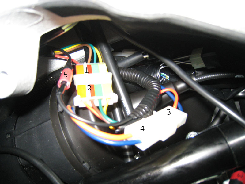
And now for some more details on that mess of connectors:
- Audiovox connector, control panel side.
- Audiovox connector, servo side.
- My Power/tach connector, Audiovox side.
- My Power/tach connector, bike side.
- My Ground wire connector (placed in the ground wire from the control panel at the same location as the Audiovox connector).
The wires from the control panel are not shortened. I tapped the (grey?) backlight power wire for the control panel directly into the red switched power wire way up near the control panel so that the backlight is always on when the ignition is on, and so there's only 5 wires to try to wrap up and hide along the handlebar.
The red power wire from (2) goes only a short distance to (3). The power and tach wires from (4) run a short distance down to the giant brain stem of stock wiring and up into the fuse/battery area where I made my power and tach signal connections almost exactly like FJRCarShopGuy did.
All wires from (2) and (3) go directly back to the the main harness on the servo (except for the red power wire, which goes from 2 to 3). All of this was cut to length (about 5 feet of excess removed!).
The ground wire from the control panel goes through the bullet connector (5) back to the servo and taps into the the ground wire coming out of the servo's main harness, very close to the servo (wiring experts: is this a wiring sin? should I be watching for grounding problems?). The ground wire from the servo follows the large coolant hose that's connected to the coolant pipe. It goes under the frame then back up on the other side where it's mounted to an existing bolt:
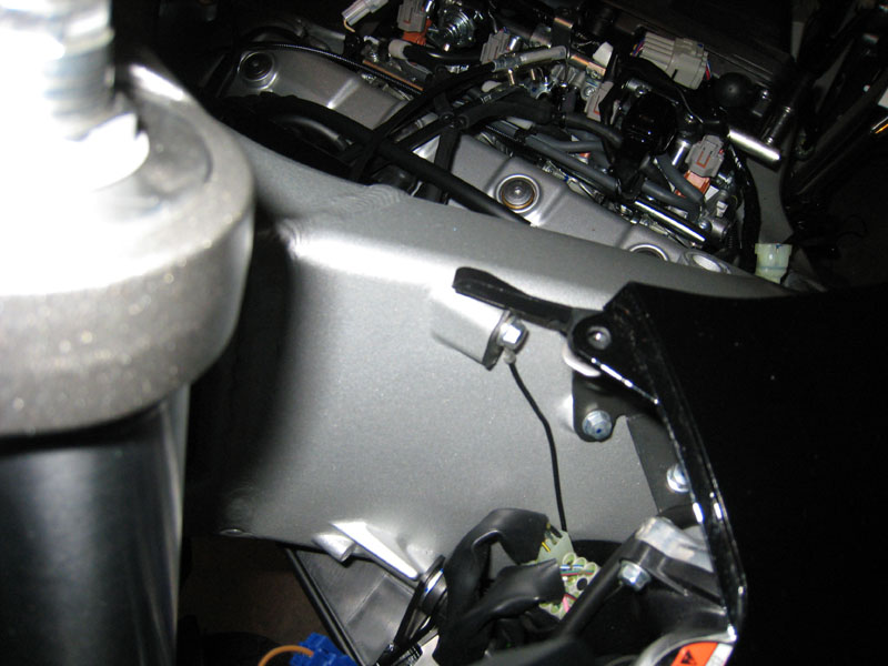
The purple and red brake wires from the servo's main harness follow the frame on the left side of the bike (in a separate conduit; visible in the first picture) to the main ECU harness area where I tapped into the stock brake wiring. I added a connector right near where I tapped into the wiring:
I like having connectors everywhere so that things can be disconnected and moved out of the way as necessary for other farkling and maintenance. The connectors came from RadioShack. I crimped AND soldered the connectors to the wires for a reliable connection.
Unfortunately, it's freezing cold and snowy here, so I can't go for a test ride to verify that everything works. My bike is still stripped down for now, so I can take more pictures of other details at your request. Feel free to ask for details that I left out or to tell me if I did something horribly wrong so that I can fix it
~Jeff
-------------- UPDATE --------------
I have since shortened the wiring more for a much cleaner appearance and to keep the wiring away from the coolant pipe:
-------------- ANOTHER UPDATE --------------
I finally added a vacuum reserve canister because the accelerate button for the cruise control was quite ineffective. The cruise control seems to engage a bit quicker now and the accelerate button actually works! I made my canister out of a 2" PVC coupler, two 2" PVC plugs and a 3/16" threaded brass nipple thing. I found a nice place for it that only required a very slight dremeling in one of the ribs on the top side of the rear fender where the canister sits (right next to the lock barrel that actuates the seat release mechanism) to allow it to fit under the tool tray:
I used some basic PVC primer and glue to glue the PVC parts together. I only inserted the plugs about half-way into the coupler to make it as long as could fit in the space under the tray. That nasty looking black junk is some silicone gasket maker I had left-over from installing my Remus hexacones, and it seems to do a good job at sealing the threads of the brass nipple. The canister was still holding vacuum when I checked today after a full 2 days of no riding.
And here's the hose from the canister where it meets up with the rest of the cruise control's vacuum hoses:
Last edited by a moderator: